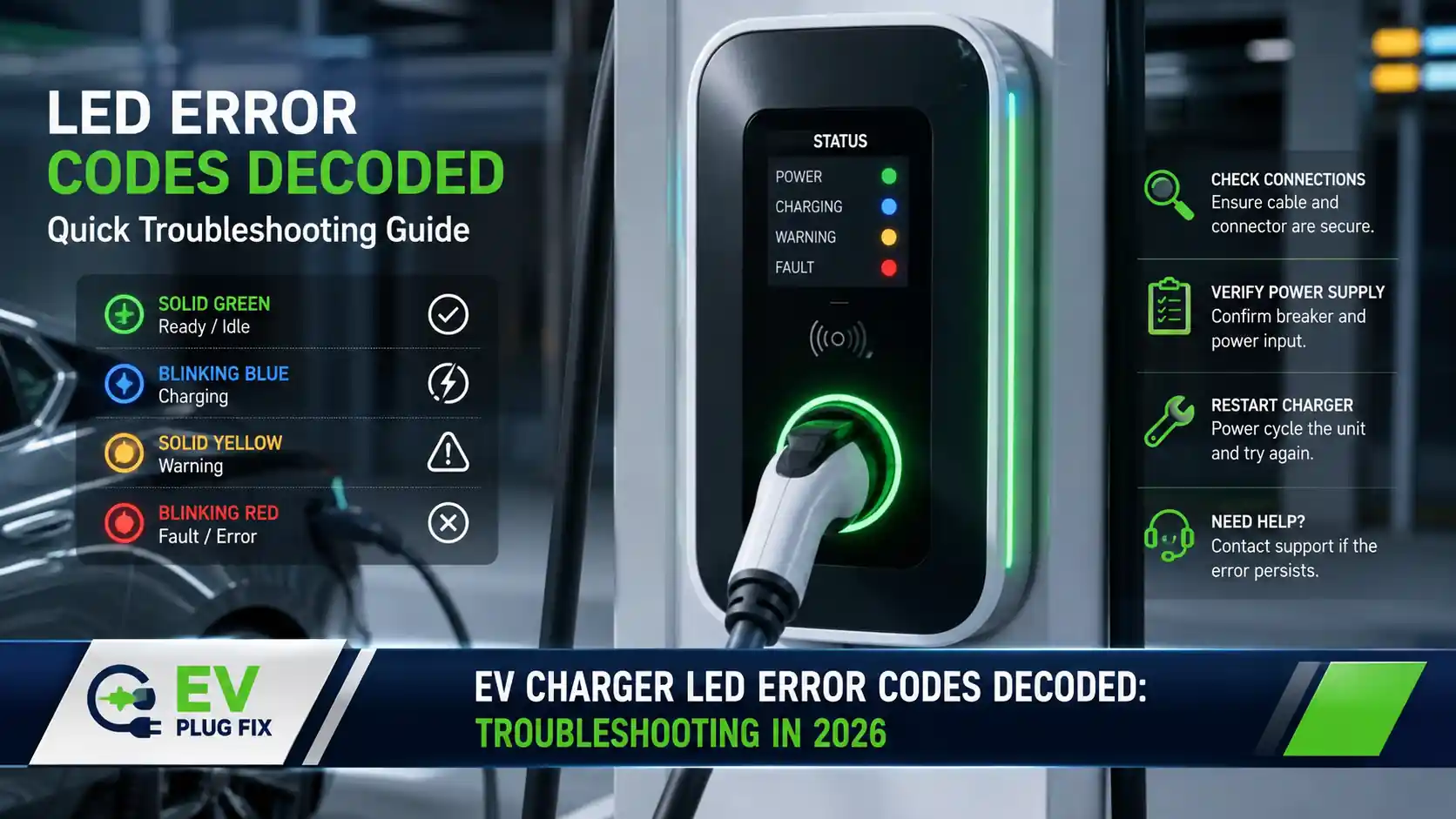
A red warning light on an EV charger usually indicates a protective shutdown rather than equipment failure. Level 2 charging stations operate under sustained high current—typically 32 to 48 amps over several consecutive hours—so their onboard monitoring systems are intentionally sensitive. When a station halts a session and begins flashing, it has detected an electrical reading outside its configured parameters.
When a charging session halts unexpectedly, the root cause typically traces back to one of three areas: the upstream electrical branch circuit, the charging unit’s internal hardware, or the vehicle’s onboard communication systems. Because modern EVSEs monitor multiple safety thresholds simultaneously, isolating which part of the installation triggered the cutoff prevents unnecessary hardware replacement and speeds up repairs.
For those planning a new dedicated charging branch, our guide to Level 2 EV charger garage installation outlines the wire sizing, conduit planning, and panel capacity needed to avoid chronic supply faults.
Why LED Indicators Have Diagnostic Limits
Status LEDs are a basic visual interface for a complex electrical device. A residential wallbox monitors ground continuity, input voltage tolerance, contactor position, and terminal temperatures. When an anomaly occurs, the unit typically relies on a single multicolor diode or a small LED array to communicate that state.
Because charging manufacturers use proprietary firmware routines, flash patterns vary significantly across brands. Two red flashes on a Tesla Gen 3 unit point toward a ground continuity problem, while a flashing red ring on a go-e charger often indicates an earthing test failure or device fuse issue. Interpreting these warnings requires checking the pattern against the manufacturer’s specific model manual and reviewing what the vehicle and home panel were doing when the session stopped.
Diagnostic Taxonomy: Where the ChargeX MRECs Fit In
Industry groups have spent significant effort trying to standardize how charging failures are defined and logged. A prominent example is the ChargeX Consortium, a multi-laboratory initiative supported by the U.S. Department of Energy and national laboratories, including Idaho National Laboratory (INL).
To reduce ambiguity in public charging networks, the ChargeX Diagnostics Task Force developed a proposed framework of 26 Minimum Required Error Codes (MRECs). These definitions (ranging from CX001 for connector lock issues through CX026 for physical cable damage) categorize faults across four primary areas of responsibility: the EV user, the charging station operator (CSO), the charging station hardware (EVSE), and the vehicle itself.
Operational Context: ChargeX MRECs are recommended data practices designed for backend communications (such as OCPP logs), vehicle telematics, and station management platforms—primarily aimed at public DC and commercial AC charging reliability. They do not govern the physical LED blink patterns programmed into residential wallboxes. Nevertheless, the ChargeX framework provides a helpful reference for categorizing the root causes behind common charging interruptions.
| ChargeX Category | Reported Condition | Common Source | Observed Field Behavior |
|---|---|---|---|
| CX001 | Connector Lock Failure | Coupler / Port Latch | Latch actuator does not seat fully; port remains unengaged. |
| CX002 | Ground Failure | Supply Circuit / Neutral Bond | Ground continuity lost, high impedance, or moisture in plug face. |
| CX003 | High Temperature | Terminal Block / Handle | Loose terminal block lugs or sustained exposure to high ambient heat. |
| CX004 | Overcurrent | Vehicle OBC / Settings | Vehicle draws current exceeding the station’s advertised pilot signal. |
| CX005 / CX006 | Over / Undervoltage | Grid / Service Panel | Voltage excursions beyond normal operating limits during heavy local demand. |
| CX013 | Network Loss | Local Wi-Fi / Backhaul | Unit operates in offline fallback mode; app reporting becomes unavailable. |
Brand-Specific LED Blink Patterns Decoded
Tesla Gen 3 Wall Connector
According to Tesla’s official service documentation for the Gen 3 Wall Connector, fault states are indicated by the top red status LED flashing in distinct count sequences, separated by a one-second pause. While firmware updates can occasionally adjust alert behaviors, standard manual codes include:
- 1 Red Blink: Ground Fault Circuit Interrupter (GFCI) trip. The unit detected current leakage to ground. Inspect the charging handle, pins, and vehicle port for moisture, debris, or damage.
- 2 Red Blinks: Ground Assurance Fault. The internal monitor detected an open or high-resistance ground path. Verify the equipment grounding conductor in the junction box or subpanel.
- 3 Red Blinks: High Temperature. Thermal sensors at the terminal block or handle exceeded operating limits. If this recurs at rated capacity, disconnect power and check the torque on the terminal block screws.
- 4 Red Blinks: Internet Connection Lost. The charger cannot reach the local Wi-Fi network. Charging can generally proceed, but scheduled network features and power-sharing communication may be limited.
- 6 Red Blinks: Overvoltage or Poor Grid Quality. The supply voltage exceeded the unit’s threshold (typically above ~260V on nominal 240V split-phase).
- 7 Red Blinks: Vehicle Overcurrent. The car drew current beyond the maximum advertised pilot limit. Amperage limits should be verified in the vehicle charge settings.
- No LEDs Lit: Complete loss of power. Check the feeder circuit breaker. If line voltage is present across L1 and L2 at the terminal block while the unit remains unlit, the internal power supply board has likely failed.
When charging non-Tesla vehicles using NACS-to-J1772 adapters, mechanical fit and pin tolerances are common points of failure. Our review of NACS vs. J1772 charging connector differences details interface tolerances and pin configurations.
go-e Charger (Gemini & Home Series)
In go-e’s operating manuals for the Gemini and Home series, the 360-degree LED ring conveys diagnostic states through color shifts and targeted flash positions:
- Blue Rotating LEDs: Standby. The wallbox is waiting for vehicle handshake confirmation or user authorization.
- Solid Cyan or Green: Active charging session in progress.
- Red Flashing at the Top of the Ring: Earth test failure. The charger’s ground test did not detect an adequate return path. On certain European supply topologies (such as IT or TT systems), the earthing test setting may require adjustment via the mobile app.
- Entire Ring Flashing Red: Internal protection fault. The unit detected an internal hardware fault, contactor mismatch, or phase imbalance.
- Unlit Ring (No Power): If input power is verified at the outlet or junction, inspect the internal micro-fuse located on the rear of the unit. A blown fuse often points to an upstream surge or an incorrect line/neutral landing during installation.
For mobile and temporary installations, our evaluation of the go-e Charger Gemini flex covers the grounding requirements and adapter checks specific to industrial socket connections.
Leviton, Alfen, and SolarEdge Indicators
Other manufacturers document fault codes through dedicated indicator arrays:
- Leviton Evr-Green Series: According to Leviton’s technical manual, the red fault LED signals issues via specific flash patterns: 1 flash indicates Input Overvoltage (OVP); 2 flashes indicate Input Undervoltage (UVP); 3 flashes represent Over-Temperature (OTP); and 6 flashes indicate a ground fault.
- Alfen Eve Series: Uses an integrated status bar. A solid red light indicates an unrecoverable fault requiring a full power reboot. Alternating red and blue indicates a user-resolvable issue, such as an improperly seated plug or an unauthorized RFID card. Alternating red and grey indicates a session ended unexpectedly by the vehicle.
- SolarEdge EV Wallbox: Solid red typically indicates an internal hardware self-test issue, while flashing red often points to an insulation fault detected on the DC side of an integrated inverter-charger setup.
To reduce peak demand strain and limit grid-voltage fluctuations, many operators pair diagnostic monitoring with automated schedules. See our guide on EV load shifting strategies and our review of PV surplus charging for balancing residential loads.
Two External Failure Points: GFCI Interactions and 12V Battery Limits
1. GFCI Breaker Interactions (UL 2231 vs. Panel Breakers)
Under Article 625 of the National Electrical Code (NFPA 70), EV charging equipment must include personnel protection. Certified Level 2 chargers incorporate a built-in Charge Current Interrupting Device (CCID) compliant with UL 2231, designed to trip when leakage current exceeds safe thresholds (typically 20 mA for CCID20 or 5 mA for CCID5).
Complications often arise when a plug-in wallbox is installed on a circuit protected by an upstream GFCI circuit breaker in the main panel—a requirement in many jurisdictions for 240V garage receptacles. Placing two sensitive ground-fault detection circuits in series on the same line can cause nuisance tripping. Test pulses sent by the charger’s internal self-check circuit can trigger the panel’s GFCI breaker, cutting power entirely and leaving a dark, unresponsive charger.
If a breaker trips immediately when a session begins, but the charger functions normally on a properly installed dedicated circuit, an electrician should evaluate whether competing GFCI devices are causing the shutdown.
2. Low Voltage in the Vehicle’s 12V Auxiliary Battery
While an EV’s traction motor relies on high-voltage DC from the main pack, the vehicle’s onboard communication computers, relays, and charge-port lock actuators run off a standard 12V auxiliary battery.
When you connect an EV charger, high voltage does not flow immediately. The station applies a 12V DC signal to the Control Pilot line to initiate the handshake. If the vehicle’s auxiliary 12V battery is depleted, degraded, or dropping under load:
- The car’s Electric Vehicle Communication Controller (EVCC) cannot initialize or command the high-voltage contactors to close.
- The motorized charge-port lock may fail to engage.
- The station registers a pilot handshake timeout, terminates the connection, and flashes a fault light.
Drivers frequently suspect their wallbox when an aging auxiliary car battery is the real issue. Cold-weather operations can accelerate this problem; our operational report on winter EV garage storage covers how low temperatures affect 12V auxiliary systems and session start reliability.
Reference Video: The Industry Effort Behind Standardized Diagnostics
For a detailed look at how standardized error definitions are structured, the presentation below features Benny Varghese of Idaho National Laboratory discussing the technical development of the ChargeX Minimum Required Error Codes:
For connected installations, matching your network setup with proper server endpoints ensures diagnostic logs are captured correctly. See our step-by-step walkthrough for go-e Controller setup for practical configuration steps.
Practical Troubleshooting Routine
Before assuming a charging station has suffered an internal breakdown, follow this sequence to isolate the cause:
- Record the Flash Sequence: Note the exact number of blinks, colors, and pause durations. Take a clear photo or short video. Check whether the vehicle’s dashboard displays a specific fault message.
- Inspect the Connector and Port: Disconnect the coupler and examine the pins for moisture, foreign debris, arcing marks, or thermal discoloration.
- Power-Cycle the Dedicated Breaker: Switch the circuit breaker to OFF, wait at least 60 seconds to allow the internal logic capacitors to discharge, and switch it back ON. Observe whether the charger completes its initial self-test.
- Verify Supply Voltage Conditions: If the unit reports a voltage fault, check whether large household loads are running. Under standard utility guidelines (such as ANSI C84.1), nominal 240V split-phase voltage typically operates within roughly ±5% (228V to 252V). Sustained drops below 215V can trip protective cutoffs.
- Check Physical Latch Engagement: Ensure the handle clicks firmly into place. A worn latch mechanism or a stiff cable can prevent the proximity pin from making full contact.
- Isolate the Problem with Another Charger: Test the vehicle at a public Level 2 station. If the vehicle charges normally, the issue is isolated to your home unit or its branch circuit. If the vehicle fails to charge there as well, the problem points toward the car’s onboard charger (OBC), locking actuator, or auxiliary battery.
- Track Recurring Issues: If a fault clears after a reset but returns regularly, do not continue resetting the breaker. Review our guide to EV charging maintenance to schedule an electrical inspection of terminations and breaker connections.
When to Stop and Call a Professional
Never open an energized charging station enclosure. Disconnect power at the main panel and call a licensed electrician immediately if you observe any of the following:
- A distinct burning or acrid electrical odor around the charging station, junction box, or receptacle.
- Thermal discoloration, scorched terminals, or melted casing components.
- A circuit breaker that trips instantly and forcefully when switched on without a vehicle connected (indicating a direct short circuit).
- A charging handle or cable that becomes excessively hot to the touch during operation.
Frequently Asked Questions
Why does an EV charger flash red as soon as the handle is plugged in?
A fault that occurs the moment the handle is connected usually points to a handshake timeout or a proximity detection failure. Common causes include an incompletely seated connector, a stuck charge-port locking pin, moisture inside the coupler, or a weak 12V auxiliary battery in the vehicle.
Can cold weather cause an EV charger error light?
Yes. Sub-zero temperatures can stiffen charging cables, making it difficult for the connector to seat deep enough to close the proximity circuit. Extreme cold also reduces the capacity of older 12V auxiliary vehicle batteries, which can prevent onboard computers from waking up to start a session.
Does a red light mean the charger’s logic board has failed?
Usually not. A flashing or solid red light indicates that the onboard logic board is powered and successfully running its protection routines. A catastrophic failure of the main logic board typically results in an unlit unit that does not respond to input power.
Why does a car charge normally at public stations but fail on a home charger?
When a vehicle accepts a charge at public stations, its onboard charging hardware is confirmed to be working. The issue at home usually involves the feeder circuit, high neutral-to-ground resistance, an upstream GFCI breaker interaction, or a high-resistance connection at the wallbox terminal block.
Bottom Line
A flashing red indicator is not proof that a charging unit is dead; it indicates that a safety limit was crossed. Charging interruptions usually divide among three areas: utility voltage or grounding conditions at the panel, internal contactor and sensor states inside the EVSE, or auxiliary battery and locking latch responses from the car.
Checking the feeder breaker, verifying supply voltage, inspecting the coupler pins for wear, and confirming the health of the vehicle’s 12V battery will isolate the majority of faults before you order replacement hardware or pull wire.
Sources and Methodology
This technical guide is based on standard electrical installation practices, manufacturer service documentation, and recognized diagnostic frameworks. Reference standards include Article 625 of NFPA 70 (National Electrical Code), UL 2231-1 and 2231-2 personnel protection standards for EV supply equipment, and ANSI C84.1 voltage tolerances. Diagnostic categorization references published documentation from the ChargeX Consortium and technical guidelines from the Open Charge Alliance.