EV Charger EMC Testing and Electromagnetic Compatibility Standards

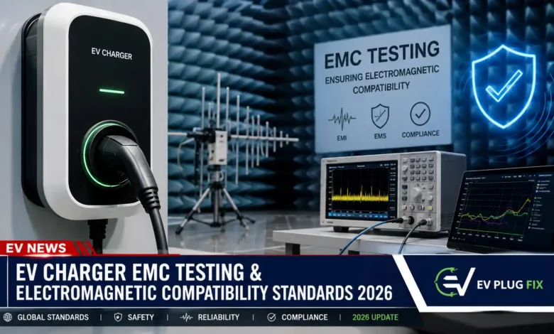
EV charger EMC testing answers two practical questions: does the equipment create excessive electromagnetic interference, and can it keep operating acceptably when exposed to disturbances from its electrical environment?
For conductive charging equipment, the first distinction to make is whether the charging electronics are on the vehicle or off-board. IEC 61851:2017 concerns the vehicle’s on-board charger, while IEC 61851:2018 covers EMC requirements for off-board conductive EV charging systems. For wallboxes, charging stations and DC fast-charging equipment, that distinction is fundamental.
The complete compliance path then depends on the charger’s architecture, interfaces, radio functions and destination market. EMC is also only one part of product compliance: electrical safety, power quality, radio regulation and, where relevant, grid-interconnection requirements need to be considered separately.
What EMC Means for an EV Charger
Electromagnetic compatibility has two main sides: emissions and immunity.
- Emissions: unwanted electromagnetic energy generated by the charger must remain within the limits that apply to the product. Disturbances may travel along power or communication cables or radiate from cables, switching circuits and the enclosure.
- Immunity: the charger is exposed to specified disturbances to check whether it continues to operate within the performance criteria required by the applicable standard.
Typical immunity testing can expose equipment to static discharge, nearby radio-frequency fields, switching transients, surges and RF disturbances coupled onto cables.
EMC is not the same as electrical safety. A charger that passes a safety evaluation has not automatically demonstrated acceptable emissions or immunity, and passing EMC testing does not by itself establish electrical safety compliance.
Why EV Charging Equipment Can Create EMI
Power converters switch voltage and current rapidly to perform functions such as AC-to-DC conversion, DC conversion and power-factor correction. Those switching transitions can generate electromagnetic energy over a broad frequency range.
Interference can then follow several paths. It may travel along AC input, DC output, control or communication wiring, while cables, enclosure openings and conductive structures can act as unintended antennas.
DC fast charging is particularly demanding because substantial power conversion occurs in the charging equipment itself. An AC wallbox has a different architecture because the vehicle normally performs the main AC-to-DC conversion, but the EVSE still contains control electronics, switching devices and often wired or wireless communications that can generate or receive interference.
Conducted, Radiated and Power-Quality Disturbances
Conducted disturbances travel through electrical conductors. Radiated disturbances propagate as electromagnetic fields from circuitry, cables and other structures. The distinction matters because a solution for one coupling path may have little effect on another. An input filter, for example, may reduce conducted noise while cable routing or a high-frequency switching loop continues to cause radiated emissions.
Power-quality effects should also be kept distinct from high-frequency EMI. Current harmonics, voltage fluctuations and flicker concern lower-frequency interaction with the electricity supply and can fall under separate IEC 61000 requirements or regional rules. They are related to electromagnetic compatibility in the broader engineering sense, but they are not interchangeable with conducted and radiated RF emissions tests.
A Practical Roadmap for Choosing the EMC Compliance Path
Before booking laboratory time, manufacturers and engineers should establish the product’s regulatory and technical classification. A useful sequence is:
- Identify where the charging equipment is located. Determine whether the EMC assessment concerns an on-board charger or off-board EV supply equipment.
- Define the target markets. A charger intended for the EU and the United States can face different legal frameworks even when much of the underlying EMC engineering is shared.
- List every external interface. Include AC and DC power ports, charging cables, Ethernet, control wiring and other signal connections.
- Identify intentional radio functions. Wi-Fi, Bluetooth, cellular and other transmitters can change the regulatory classification and add radio-specific requirements.
- Select the applicable product standards and legislation. Start with the standards relevant to the complete product rather than assembling a test program from isolated basic EMC standards.
- Define operating modes and worst-case configurations. Charging power, cable arrangement, communications activity, bidirectional operation and other states can affect emissions and immunity behavior.
- Build the laboratory plan from those requirements. Confirm the required tests, ports, limits, severity levels, configurations and performance criteria before formal testing begins.
This process avoids a common mistake: treating EMC compliance as a generic checklist that is identical for every charger and every market.
Which EMC Standard Applies to Off-Board EV Chargers?
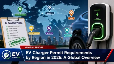
For conductive EV supply equipment, IEC 61851:2018 is a central international EMC standard. Its scope covers EMC requirements for off-board components or equipment used to supply or charge electric vehicles through conductive power transfer.
The standard covers off-board charging equipment associated with Modes 1, 2, 3 and 4 as defined by IEC 61851 It addresses EMC-related requirements including test arrangements, ports and operating conditions.
| Standard or regulation | Primary relevance | Important distinction |
|---|---|---|
| IEC 61851:2018 | EMC for off-board conductive EV charging equipment | The principal IEC 61851 EMC document to examine for EVSE and charging stations |
| IEC 61851:2017 | EMC requirements for an EV’s on-board charger during conductive connection to a supply | It is not the general EMC standard for an off-board charging station |
| IEC 61000 family | EMC test methods, environments and certain emission, immunity and power-quality requirements | Individual parts address different phenomena; IEC 61000 is not one universal EVSE compliance test |
| EU Directive 2014/30/EU | EU legal framework for electromagnetic compatibility where it applies to the equipment | Product classification and other applicable Union legislation must be established before selecting the conformity route |
| EU Directive 2014/53/EU | Radio Equipment Directive for products that qualify as radio equipment | RED includes an EMC essential requirement as well as radio-spectrum and other applicable requirements |
| FCC Part 15 | US regulation of radio-frequency devices, including intentional and unintentional radiators | Primarily addresses RF emissions, operation and equipment authorization rather than providing a general IEC-style EVSE immunity regime |
Check the Standard Edition and Scope
Standard numbers alone are not enough. The edition and scope need to match the equipment being assessed.
As of August 2026, IEC has not published a replacement edition identified as IEC 61851:2026. The IEC catalogue continues to identify IEC 61851:2017 as Edition 1.0 for on-board charger EMC and IEC 61851:2018 as Edition 1.0 for off-board charging-system EMC.
The IEC catalogue lists a 2026 stability date for IEC 61851:2017. A stability date should not be interpreted as a guarantee that no standards-development or revision activity exists. For an actual certification project, check the IEC catalogue and the relevant national or regional adoption for current editions, amendments and transition arrangements.
Likewise, claims about new frequency limits, bidirectional-charging provisions or other requirements should be traced to an identifiable published standard, amendment or applicable regulatory document rather than inferred from a year attached to a standard number.
How the IEC 61000 Series Fits In
IEC 61000 is a large family of standards. Its basic immunity standards provide test methods that product standards can call upon rather than forming a single stand-alone EV charger certification program.
| Test method | What it represents in practice |
|---|---|
| IEC 61000 | Electrostatic discharge, such as static electricity transferred when a person touches or approaches accessible parts |
| IEC 61000 | Radiated RF fields from nearby transmitters and other radio-frequency sources |
| IEC 61000 | Fast repetitive electrical transients associated with switching activity in electrical systems |
| IEC 61000 | Higher-energy surge events associated with phenomena such as switching and lightning-related coupling |
| IEC 61000 | RF disturbances coupled onto connected cables rather than arriving primarily as a radiated field |
The applicable EV charging standard determines which methods are required, where disturbances are applied, the test levels and what constitutes acceptable charger behavior. Engineers should therefore work from the applicable product requirements rather than assume every IEC 61000 method must be performed at one universal severity level.
EU Versus US Market Access: What Changes?
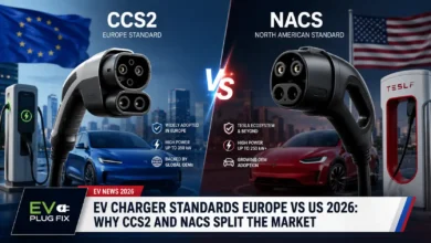
The underlying engineering challenge remains similar in both markets: control RF emissions and make the charger robust enough for its intended electromagnetic environment. The legal route, however, is different, as are broader EV charger standards in Europe and the US.
European Union
For equipment within its scope, Directive 2014/30/EU, the EMC Directive, requires electromagnetic disturbances to be controlled and the equipment to have adequate immunity for its intended use. Harmonised standards whose references are published for the relevant requirements can provide a route to presumption of conformity.
However, manufacturers should not automatically assume that the EMC Directive and radio legislation simply apply side by side to every connected charger. Product classification comes first.
A charger incorporating Wi-Fi, Bluetooth, cellular connectivity or another intentional radio function may qualify as radio equipment under Directive 2014/53/EU, the Radio Equipment Directive. RED Article 3(1)(b) requires radio equipment to provide an adequate level of electromagnetic compatibility corresponding to the objectives of Directive 2014/30/EU. EU legislation also provides that where EMC essential requirements are laid down more specifically by other Union legislation, the EMC Directive does not separately apply to those requirements.
In practice, the manufacturer must determine whether EMC conformity for the complete product is assessed under the EMC Directive, RED or another applicable piece of Union harmonisation legislation, and then identify the standards and conformity procedures relevant to that classification.
United States
For the US market, FCC Part 15 is relevant to radio-frequency devices and distinguishes, among other categories, intentional and unintentional radiators.
Digital circuitry in an EV charger may place the relevant device or subsystem within requirements for an unintentional radiator, subject to the FCC’s definitions, exemptions and product classification. That does not mean every EVSE control circuit automatically follows exactly the same authorization procedure.
Most intentional radiators generally require FCC certification. Many unintentional radiators are generally authorized through the Supplier’s Declaration of Conformity procedure, although the applicable route depends on the particular device classification and FCC rules.
The important distinction is that FCC compliance is not equivalent to complete IEC-style EMC qualification. Part 15 principally addresses radio-frequency emissions, operation and equipment authorization for devices within its scope. It does not establish a general EVSE immunity test regime equivalent to the immunity requirements that can apply under IEC 61851
A charger being prepared for both EU and US sale therefore needs a market-specific compliance plan rather than a simple assumption that passing one region’s EMC program automatically satisfies the other.
What Happens During EV Charger EMC Testing?
The laboratory program normally combines emissions measurements with immunity tests while the charger operates in configurations specified by the applicable requirements. Engineers also monitor whether charging, communications, controls and safety-related functions behave within the required performance criteria.
| Test category | What the test examines or simulates | What engineers watch |
|---|---|---|
| Conducted emissions | RF energy leaving the charger through power or other tested cable interfaces | Emission levels at the relevant ports across the specified frequency range |
| Radiated emissions | Electromagnetic energy radiated by circuitry, cables and the enclosure | Field-strength measurements and the effect of cable layout, operating mode and orientation |
| Electrostatic discharge | Static-electricity events at accessible or specified coupling locations | Resets, communication loss, charging interruption, incorrect control behavior and recovery |
| Fast transient/burst | Rapid repetitive disturbances associated with electrical switching | Whether control and charging functions remain within the required performance criteria |
| Surge | Higher-energy electrical transients | Functional disruption, component stress and required recovery behavior |
| Radiated RF immunity | Exposure to electromagnetic fields from nearby RF sources | Charging control, communications, sensing and other monitored functions |
| Conducted RF immunity | RF interference coupled onto cables | Susceptibility of power, signal and communication interfaces |
Conducted-emissions measurements often use controlled impedance networks and measurement receivers. A LISN, or line impedance stabilization network, is common for many mains-port measurements, but EV charging standards can specify other artificial networks or arrangements depending on the interface and charging configuration.
Radiated-emissions testing uses calibrated antennas and receivers in a compliant test environment. Cable placement, load, communications activity and equipment orientation can influence the result, which is why standardized setup details matter.
Immunity testing is not simply a pass-or-fail check for catastrophic failure. Depending on the applicable performance criteria, engineers may need to monitor temporary degradation, recovery, communication behavior and whether the charger continues to perform the functions required during or after the disturbance.
Designing an EV Charger for EMC Compliance
EMC failures are generally easier to prevent during electrical and mechanical design than to repair after formal testing. Filtering is important, but it is only one part of the design.
- Minimize high-frequency current loops: Keep switching paths compact to reduce magnetic coupling and radiation.
- Control switching edges: Gate-drive and switching behavior can influence high-frequency emissions, although changes need to be balanced against switching losses, efficiency and thermal performance.
- Design filters for the actual noise path: Common-mode and differential-mode disturbances behave differently, so components should be selected and placed according to the problem being controlled.
- Plan grounding and bonding carefully: PCB return paths, protective-earth arrangements, chassis bonding and connections between assemblies can strongly influence both emissions and immunity.
- Treat cables as part of the EMC design: Power, charging and communication cables can carry interference and can also become effective radiating or receiving structures.
- Use shielding where it solves a defined coupling problem: Enclosures, cable shields and internal barriers can help, but seams, apertures and poor shield termination can significantly reduce their effectiveness.
- Separate noisy and sensitive circuits: High-current switching stages should be physically and electrically managed so that noise is not unnecessarily coupled into sensing, control and communication circuits.
- Pay attention to connector and enclosure transitions: A well-designed PCB can still perform poorly if high-frequency current is forced through long bonding paths, poorly terminated shields or large enclosure openings.
- Include communications in pre-compliance testing: Ethernet, control buses, payment hardware and wireless modules can introduce additional coupling paths and operating states.
- Test representative hardware early: Pre-compliance measurements can expose dominant emissions and immunity weaknesses before enclosure tooling and production design choices become difficult to change.
There is no credible universal attenuation figure for an EV charger EMI filter. Actual performance depends on frequency, source and load impedance, topology, parasitic effects, component placement, cabling and the measurement arrangement. A filter specification or isolated attenuation figure should therefore not be treated as proof that the complete charger will pass EMC testing.
Do SiC and GaN Make EMC Harder?
Silicon-carbide and gallium-nitride power devices can support fast switching and high-efficiency, high-power-density converter designs. Faster voltage and current transitions can also increase high-frequency spectral content and common-mode currents if parasitic capacitance, inductance, layout and cabling are not controlled.
That does not mean a SiC or GaN charger automatically has an EMC problem, nor does it mean all wide-bandgap converters operate at the same switching frequency. Switching frequency and edge rate depend on topology, power level, magnetics, thermal constraints, efficiency targets, device characteristics and control strategy.
The practical challenge is to manage the complete high-frequency current path rather than focusing on the semiconductor technology in isolation.
Bidirectional Charging Adds More Operating States
Vehicle-to-grid and vehicle-to-home systems can transfer power from the vehicle toward a building or electricity network as well as into the vehicle. Those additional operating states can change converter activity and therefore the conditions that produce worst-case emissions or susceptibility.
Manufacturers need to determine which operating modes are relevant to the applicable EMC evaluation. Bidirectional equipment can also face grid-interconnection, communications, functional and electrical-safety requirements that are separate from EMC.
V2G compliance should therefore not be reduced to one supposed new EMC test. The complete architecture and its intended market determine the applicable compliance program.
Wireless Charging Is a Different EMC Problem
Wireless EV charging intentionally transfers substantial power through electromagnetic coupling across an air gap. That creates EMC and electromagnetic-field considerations that differ significantly from conventional conductive charging.
Wireless charging systems need to be assessed against standards and regulatory requirements applicable to wireless power transfer. IEC 61851 should not be assumed to provide the complete compliance framework for a wireless charging system.
What Buyers Should Check on an EV Charger
Consumers and charging-site operators do not need to interpret laboratory plots, but they should verify that the charger is legitimately intended for the market in which it will be installed.
- Look for the conformity markings and regulatory information required in the destination market.
- Check manufacturer compliance documentation rather than relying solely on a retailer’s statement that a charger is “EMC certified.”
- Make sure declarations and certificates correspond to the actual charger model and relevant configuration.
- For commercial procurement, request the applicable standards and conformity documentation when compliance is a contractual requirement; these checks are especially important when evaluating certified EV chargers for volume supply.
- Do not assume an electrical safety listing automatically demonstrates compliance with separate EMC or radio requirements.
Installation also matters. Grounding, cable routing, accessories and other installation details should follow the manufacturer’s instructions because the installed configuration can affect both electrical safety and electromagnetic performance.
Essential Questions & Expert Answers
What is the main EMC standard for an off-board conductive EV charger?
IEC 61851:2018 is a key international standard covering EMC requirements for off-board conductive EV charging systems. It is not the only requirement that can apply to a finished charger, because regional legislation and other product requirements must also be considered.
Is IEC 61851 the EMC standard for charging stations?
Not generally. IEC 61851:2017 applies to on-board charging equipment associated with the vehicle during conductive connection to an AC or DC supply. IEC 61851:2018 addresses off-board conductive EV charging equipment.
Has IEC published IEC 61851:2026?
As of August 2026, IEC has not published a replacement edition identified as IEC 61851:2026. The IEC catalogue continues to list IEC 61851:2017 as Edition 1.0. Its listed 2026 stability date should not be confused with the publication of a new 2026 edition.
What is the difference between conducted and radiated EMI?
Conducted disturbances travel along cables and other conductors, while radiated disturbances propagate as electromagnetic fields. Because the coupling paths differ, measurement methods and effective mitigation techniques can also differ.
Does FCC Part 15 replace IEC EMC testing for US chargers?
No. FCC Part 15 addresses radio-frequency devices, emissions, operation and equipment authorization within its scope. It does not provide a general EVSE immunity-testing framework equivalent to IEC-style EMC immunity requirements. Other US product, electrical and safety requirements can apply separately.
Does every EV charger with digital electronics require the same FCC authorization?
No. The applicable FCC classification and authorization route depend on the circuitry, radio functions, device category and any relevant exemptions. Many unintentional radiators are generally handled through Supplier’s Declaration of Conformity, while intentional radiators generally require certification.
Does adding Wi-Fi or Bluetooth change EU EMC compliance?
It can change the product’s regulatory classification. A charger incorporating an intentional radio function may qualify as radio equipment under Directive 2014/53/EU. RED includes an EMC essential requirement corresponding to the objectives of the EMC Directive, so manufacturers should determine the applicable Union legislation before selecting the conformity-assessment route.
Can an EMI filter guarantee that a charger will pass EMC testing?
No. Filtering is only one element of EMC design. PCB layout, switching loops, grounding and bonding, shielding, enclosure construction, cable routing, interfaces and operating modes can all affect the final result.
Bottom Line
EV charger EMC testing should be approached as part of a broader compliance plan rather than as one generic laboratory test. For conductive charging, the first useful distinction is simple: IEC 61851 concerns on-board charging equipment, while IEC 61851 concerns off-board charging systems.
From there, keep four compliance areas conceptually separate. Electrical safety addresses hazards such as electric shock and other safety risks. EMC addresses electromagnetic emissions and immunity. Power-quality requirements can address effects such as harmonics, voltage fluctuations and flicker. Radio regulation applies when circuitry intentionally transmits RF energy and can also impose requirements on other RF devices.
The exact route depends on the charger’s architecture and destination market. An EU charger with an intentional radio function may need its EMC conformity addressed through the Radio Equipment Directive rather than treating RED and the EMC Directive as automatically cumulative requirements. In the United States, FCC Part 15 can govern RF emissions and equipment authorization but should not be mistaken for a complete EVSE immunity program.
For engineers, the most effective approach is to identify the regulatory path early and design the PCB, power converter, grounding, enclosure, cables and communications as one electromagnetic system. For buyers, the practical task is simpler: choose equipment with appropriate, model-specific regulatory and conformity documentation for the market where it will actually be installed.
Source Transparency
This article was checked against primary information from the International Electrotechnical Commission, including the published scopes and catalogue information for IEC 61851:2017 and IEC 61851:2018, together with relevant IEC 61000 standards. European regulatory descriptions were checked against Directive 2014/30/EU and Directive 2014/53/EU. US regulatory descriptions were checked against Federal Communications Commission information on Part 15 radio-frequency devices and equipment authorization.
Standards and regulations can be amended, superseded or implemented differently across markets. Manufacturers, laboratories and compliance engineers should verify current editions, amendments, harmonised or nationally adopted standards, transition arrangements and market-specific legal requirements before establishing a certification program.