
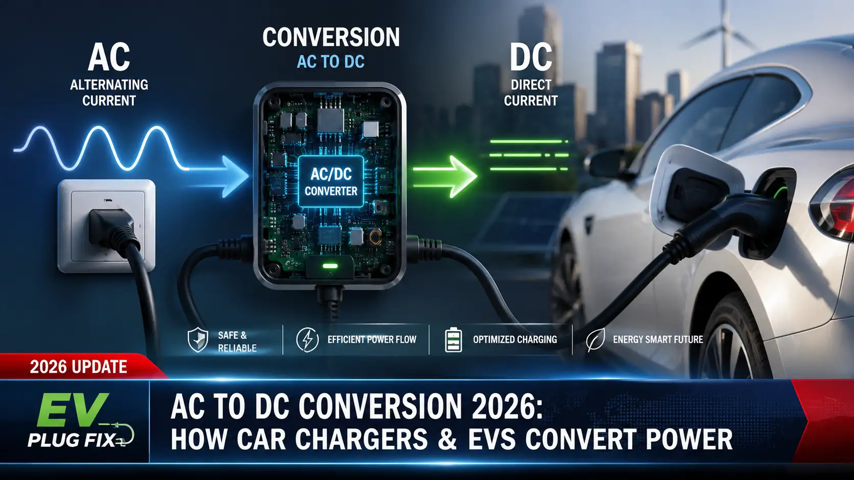
An electric vehicle battery stores energy as direct current, but homes and most electrical grids supply alternating current. Somewhere between the grid and the battery, that AC electricity therefore has to be converted into carefully controlled DC power.
Where the conversion takes place depends on how the car is being charged. With ordinary AC charging, including home Level 1 and Level 2 charging, the conversion normally happens inside the vehicle’s on-board charger. With DC fast charging, large power-electronic converters inside the charging station perform the AC-to-DC conversion instead, and controlled DC power is supplied to the vehicle.
This distinction matters because it explains why installing a more powerful home charging station does not automatically make a car charge faster, why DC fast charging can operate far beyond the power rating of an on-board charger, and why the equipment on the wall is not necessarily the component actually converting AC into battery-ready DC.
AC and DC Have Different Jobs in an EV
Alternating current periodically changes direction. Electrical grids use AC extensively because its voltage can be transformed efficiently for transmission and distribution. Grid frequency is generally 60 Hz in places such as the United States and 50 Hz in many other markets.
Direct current flows with a defined polarity rather than reversing direction with every grid cycle. An EV’s high-voltage traction battery is fundamentally a DC energy-storage system, so charging the battery requires controlled DC voltage and current.
EVs convert electrical power in several directions during normal operation. While charging from an AC source, the on-board charger converts AC into DC. During driving, the traction inverter converts battery DC into controlled AC waveforms for an AC traction motor in most modern EV architectures. During regenerative braking, power flows back through the drivetrain electronics so recovered energy can be returned to the battery.
Where Does AC to DC Conversion Happen During EV Charging?
| Charging method | Power supplied to vehicle | Where AC-to-DC conversion occurs | Key charging limit |
|---|---|---|---|
| AC Level 1 | AC | Inside the vehicle’s on-board charger | Available circuit power and vehicle AC acceptance |
| AC Level 2 | AC | Inside the vehicle’s on-board charger | Lower of EVSE supply capability and vehicle AC acceptance |
| DC fast charging | DC | Primarily inside the off-board charging equipment | Vehicle, charger, battery conditions and charging curve |
This is the most important concept to understand. A home Level 2 unit is commonly called an EV charger in everyday conversation, but its primary job is to provide and control access to AC electricity safely. The vehicle’s on-board electronics perform the conversion required to charge the high-voltage battery.
A DC fast charger works differently. Its power-conversion hardware is outside the car. The station converts incoming electrical power into the high-voltage DC requested by the vehicle and supplies it through the DC charging connection.
How an EV On-Board Charger Converts AC to DC
The traditional four-step explanation used for simple power supplies—transformer, rectifier, filter and voltage regulator—is useful for learning basic electronics, but it does not accurately describe the architecture of many modern EV on-board chargers.
Automotive on-board chargers are high-power switch-mode converters. Their exact architecture varies by manufacturer and vehicle, but a conventional design commonly contains an input filtering and protection section, an active AC-to-DC stage with power-factor correction, an intermediate DC link, and an isolated high-voltage DC-to-DC conversion stage.
Input Filtering and Protection
Before significant power conversion takes place, the incoming AC passes through circuitry designed to manage electromagnetic interference and protect the charging system. The charger must operate without creating unacceptable electrical noise while also coping with conditions that can occur on the AC supply.
Temperature, voltage and current are monitored throughout the charging system. The vehicle can reduce power or stop charging when conditions move outside permitted limits.
Active Rectification and Power-Factor Correction
The first major conversion stage changes grid AC into an intermediate DC voltage. Modern high-power converters commonly use actively controlled semiconductor switches rather than relying only on the simple diode bridge associated with introductory power-supply diagrams.
Power-factor-correction circuitry also shapes the current drawn from the AC source. A well-designed PFC stage allows the charger to use the electrical supply effectively while reducing undesirable current distortion.
Different designs use different switching arrangements. Semiconductor suppliers document architectures including totem-pole, Vienna and other active converter topologies, so there is no single rectifier circuit that describes every EV.
The DC Link
After the input conversion stage, many conventional on-board charger architectures maintain an intermediate high-voltage DC bus. Energy-storage components and control circuitry stabilize this DC link before energy moves through the next conversion stage.
Not every future or specialized charger has to follow this exact layout. Power-electronics companies continue to develop more integrated and single-stage approaches, and newer automotive power-electronics designs increasingly use silicon-carbide devices, while gallium-nitride devices are also being developed and adopted for some high-frequency charger designs.
Isolated DC-to-DC Conversion
The battery cannot simply be connected to the intermediate DC bus. The charger still has to regulate its output for the battery pack and, in many designs, provide galvanic isolation between the grid side and the high-voltage battery side.
An isolated DC-to-DC stage performs this task. Industry designs can use resonant LLC or CLLLC converters, dual-active-bridge circuits and other topologies depending on the required voltage range, bidirectional capability, efficiency, cost and packaging constraints.
The output is therefore not merely generic DC. It is controlled high-voltage DC whose voltage and current can be adjusted to meet the vehicle’s charging requirements.
What the Battery Management System Does
The on-board charger does not independently decide how hard to charge the battery. Charging is coordinated with the vehicle’s battery management and other control systems.
The vehicle monitors parameters including pack voltage, current, temperature and state of charge. The charging system then operates within the limits established for the battery and vehicle.
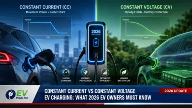
That is one reason charging power changes during a charging session. As conditions change, particularly battery temperature and state of charge, the vehicle can request or permit different amounts of power; the relationship between constant-current and constant-voltage charging helps explain how those limits evolve as the battery fills.
Why Your On-Board Charger Limits Level 2 Charging Speed
With AC charging, available charging power is constrained by both sides of the connection. The electrical circuit and EV supply equipment must be capable of supplying the power, and the vehicle’s on-board charger must be capable of accepting it.
Suppose a Level 2 installation can provide more AC power than a particular EV can accept. The car will not automatically consume the station’s full rating. Its on-board charger remains one of the limiting factors.
The reverse also applies. A vehicle with a high-capacity on-board charger cannot use that full capacity when connected to an AC source that provides less power.
For this reason, EV owners comparing home charging equipment should check the vehicle’s maximum AC charging rate before paying for electrical upgrades intended solely to increase charging speed. A higher-rated EVSE can still provide useful future capacity, but it cannot override the present vehicle’s AC charging limit.
What Changes During DC Fast Charging?
DC fast charging moves the large AC-to-DC converter out of the vehicle and into the charging station. This is one of the main reasons a DC charging site can provide substantially more power than a typical passenger EV accepts through its on-board AC charger.
Instead of sending normal AC charging power through the vehicle’s OBC, the off-board charger supplies controlled DC for the high-voltage battery system. Communication between the charger and vehicle establishes the voltage and current the vehicle can accept.
The phrase bypasses the on-board charger is useful shorthand, although the complete vehicle charging system still includes contactors, monitoring electronics, battery-management functions and other high-voltage components. DC electricity is not simply connected to the battery without vehicle supervision.
The U.S. Department of Energy’s Alternative Fuels Data Center currently describes DC fast-charging equipment with power outputs up to 500 kW, although actual charging power depends on the vehicle, battery state and charger. Battery temperature, the vehicle’s charging curve and other operating conditions can reduce the power seen during an individual session.
Why DC Fast Charging Slows as the Battery Fills
A common misconception is that a charger rated for a particular power should deliver that number throughout the entire session. EV batteries do not normally charge that way.
Maximum charging power is generally available only under appropriate battery and charger conditions. The vehicle follows a charging curve rather than maintaining maximum station power from an empty battery all the way to full.
As state of charge rises, allowable charging power commonly decreases. Temperature can also have a major effect. A cold battery may initially accept substantially less power, while excessive battery temperature can also cause the vehicle to reduce the charging rate; EV battery thermal management is therefore an important part of understanding real-world fast-charging performance.
Consequently, peak kilowatt ratings are useful for comparison but do not tell you how long an actual charging stop will take. The vehicle’s charging curve and the conditions under which it can sustain higher power are often more informative.
Does a Home EV Charger Convert AC to DC?
Usually not when discussing conventional Level 1 or Level 2 charging equipment. The equipment supplies AC to the vehicle, while the vehicle’s on-board charger performs the AC-to-DC conversion.
This terminology causes confusion because manufacturers, retailers and drivers routinely call wall-mounted EVSE a “charger.” In normal conversation that term is understandable, but technically the major battery-charging power conversion for conventional AC charging takes place in the car.
A DC fast-charging station is much closer to the technical meaning of an external charger because the station itself contains the major power-conversion stages that produce the DC supplied to the vehicle.
Does Better AC to DC Conversion Protect the EV Battery?
It is misleading to suggest that buying a premium home EVSE directly protects the traction battery by giving it “cleaner DC.” During normal AC charging, the home unit is not producing the battery’s DC charging voltage in the first place.
The EV’s own on-board charger and battery-control systems manage conversion and battery charging. A properly installed, compatible EVSE is still important for electrical safety, reliable operation and supplying the required current, but it does not replace the vehicle’s battery-management functions.
Battery aging is influenced by factors including chemistry, temperature, state of charge, time spent at high state of charge, cycling depth and charging conditions. It should not be reduced to the supposed quality of an external Level 2 unit’s AC-to-DC conversion.
Does Conversion Waste Electricity?
Yes. No practical power converter is completely lossless. Some incoming energy becomes heat in semiconductor switches, magnetic components, wiring, filters and other electronics. Battery heating, cooling, pumps and vehicle electronics can add further energy consumption during a charging session.
This explains why energy measured at the wall is not necessarily identical to the increase in usable energy stored in the battery.
Conversion losses also influence charger design. Higher efficiency reduces the heat that must be removed, which can help engineers make power electronics smaller and more power-dense. Newer automotive power-electronics designs increasingly use silicon-carbide devices, while gallium-nitride devices are also being developed and adopted for some high-frequency charger designs where their characteristics, cost and packaging make sense.
What AC to DC Conversion Means When Choosing a Home Charger
You do not need to evaluate rectifier topologies or semiconductor switching frequencies to choose home charging equipment. The useful lesson is much simpler: match the supply to what the vehicle can actually use. A broader home EV charging guide can help put charging speed, electrical capacity and equipment selection into practical context.
- Check the EV’s maximum AC charging rate. This establishes how much AC power the vehicle’s on-board charger can accept under appropriate conditions.
- Check the available electrical supply. Circuit capacity, service capacity and applicable electrical requirements determine what can be installed safely.
- Do not assume a larger EVSE rating means faster charging. The car will remain limited by its own AC charging capability when that capability is lower than the power the EVSE can provide.
- Consider future vehicles separately from today’s charging speed. A higher-capacity EVSE may make sense when planning for another EV later, but that does not increase the present vehicle’s on-board charger limit.
- Treat DC charging separately. A vehicle may accept far more power from a compatible DC fast charger than through its on-board AC charger because the large AC-to-DC conversion system is off-board.
- Use the vehicle manufacturer’s specifications. AC acceptance and DC fast-charging capability vary significantly among vehicles and can differ by model year, configuration and market.
Essential Questions & Expert Answers
Does an EV battery use AC or DC?
The traction battery stores and supplies electrical energy as DC. Other parts of the vehicle convert that DC as needed, including the traction inverter that powers an AC motor in most modern EVs.
Does Level 2 charging send DC to the car?
No. Conventional Level 2 charging supplies AC to the vehicle. The vehicle’s on-board charger converts that AC into controlled DC for the traction battery.
Does DC fast charging use the car’s on-board charger?
The high-power AC-to-DC conversion is performed by the off-board charging equipment rather than by the vehicle’s normal AC on-board charger. The vehicle still controls and supervises the charging process through its high-voltage and battery-management systems.
Will an 11 kW home charger make every EV charge at 11 kW?
No. The vehicle must support that AC charging power, and the electrical installation must also be capable of supplying it. Charging power is limited by the weakest relevant part of the AC charging path.
Why can an EV accept much more power from a DC charger?
DC fast charging avoids depending on the vehicle’s relatively compact on-board charger for the main AC-to-DC conversion. Large stationary power electronics perform the conversion instead, although the vehicle still determines how much DC charging power it will accept at any point in the session.
Bottom Line
AC-to-DC conversion is fundamental to EV charging, but the most useful question is not simply how AC becomes DC. It is where the conversion happens.
During Level 1 and Level 2 AC charging, the vehicle’s on-board charger converts grid AC into controlled DC for the traction battery. Its maximum rating can therefore limit charging speed even when the connected EVSE could supply more power.
During DC fast charging, the major conversion hardware moves outside the vehicle. The station supplies high-voltage DC while the EV supervises the process and specifies acceptable charging conditions.
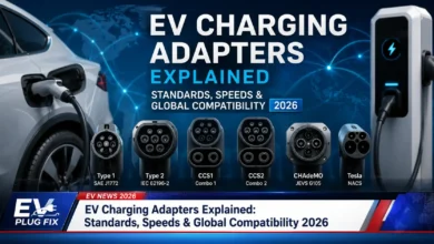
For a home-charging purchase, check the vehicle’s AC charging specification before choosing equipment based only on the largest advertised kilowatt number. For road-trip charging, look at the vehicle’s DC charging capability and charging curve rather than confusing that figure with its on-board AC charger rating; connector compatibility is a separate consideration covered in the EV charging connector types guide.
Source Transparency
This article distinguishes basic power-supply theory from the architecture used in modern EV charging systems. Technical descriptions were checked against the U.S. Department of Energy Alternative Fuels Data Center, SAE International material covering conductive and off-board DC charging, and automotive power-electronics documentation from Texas Instruments and Infineon Technologies.
Useful primary and technical references include the U.S. Department of Energy Alternative Fuels Data Center charging guide, the AFDC definition of an on-board charger, SAE J1772, SAE J2847/2 on off-board DC charging communication, Texas Instruments’ bidirectional on-board charger reference design, and Infineon’s on-board charging technical overview.
Individual EV charging capabilities, connector support and electrical requirements can vary by model, configuration and market. Vehicle specifications and installation requirements should therefore be confirmed with the vehicle manufacturer and a qualified electrical professional before equipment is purchased or installed.