
Surplus Solar EV Charging: How to Use Excess PV Power for Your Car

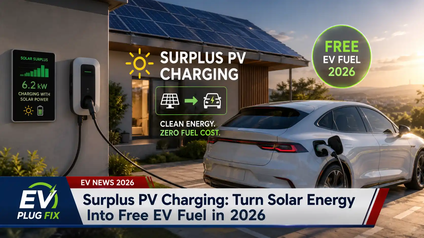
Surplus solar EV charging uses electricity that your photovoltaic system is producing beyond the immediate needs of your home to charge an electric car. Instead of automatically exporting all of that excess generation to the grid, a compatible charging system adjusts the EV’s charging rate to make use of some or all of the available surplus.
The idea is simple, but whether it saves money depends on more than sunshine. Your electricity tariff, export compensation, vehicle availability during solar-producing hours, PV system size and the charger’s control capabilities all affect the result.
It is also important to distinguish genuine surplus charging from ordinary scheduled charging. A timer can tell a car to charge at noon. A surplus-aware system measures the home’s energy flow and changes charging power as solar production and household demand change.
How Surplus Solar EV Charging Works
A typical home PV system first supplies loads operating inside the property. When solar generation exceeds household consumption, the remaining electricity can be exported to the grid, stored in a home battery or directed to another flexible load such as an EV.
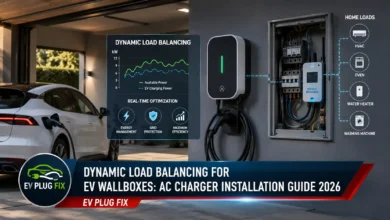
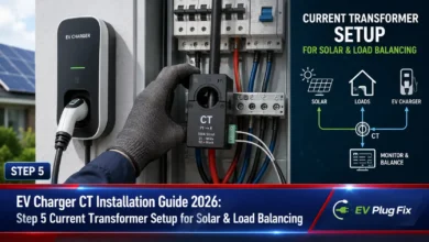
A solar-aware EV charger normally relies on an energy meter or compatible monitoring system installed at an appropriate point in the electrical installation. This often involves current-transformer installation or another supported metering method so the system can determine whether the property is importing electricity from or exporting electricity to the grid.
When sufficient surplus appears, the charger can increase the current supplied to the vehicle. If somebody turns on an electric oven, heat pump or another large load, the available surplus falls and the charger can reduce its output. Depending on the equipment and selected charging mode, it may pause charging, allow a limited amount of grid supplementation or change the renewable-energy target rather than following one universal control strategy.
This control is particularly useful because rooftop PV production rarely remains constant. Clouds, shading and changing household demand can alter the available surplus throughout the day.
What Equipment Do You Need?
You do not necessarily need a home battery or a particular brand of solar inverter. You do, however, need a charging and monitoring setup capable of coordinating the energy flows in your installation. Some chargers can work from independent import/export metering, while others require a compatible inverter, energy meter, home energy management platform or products from the same ecosystem for their solar functions to operate.
- A solar PV system: The array must generate more electricity than the home’s other loads at least some of the time if you want true surplus-only charging.
- A compatible EV charger: The charger needs a solar-surplus function or another supported method of accepting dynamic charging commands.
- Energy measurement: A meter, current transformers or another supported monitoring device measures import and export at the property connection.
- A compatible control system: Depending on the product, the charger itself, an inverter ecosystem or a home energy management system may decide how much power should be allocated to the EV.
- A compatible vehicle: The EV must accept AC charging within the range commanded by the charging system and behave reliably when the current changes or charging is paused and restarted.
The Minimum-Power Limit Matters
Surplus charging cannot necessarily track arbitrarily small amounts of excess solar generation. Under IEC 61851-type AC charging, the normal minimum current advertised to a vehicle is approximately 6 A. On a 230 V single-phase supply, that corresponds to roughly 1.4 kW.
That means a system operating in a strict solar-only mode commonly needs around 1.4 kW of genuine surplus before continuous single-phase charging can begin. If the available PV surplus is only a few hundred watts, the charger normally cannot simply instruct the car to consume that amount. Depending on its design and settings, it may wait, pause charging or add some electricity from the grid.
The EV matters as well as the wallbox. Vehicles differ in how they respond to low charging currents, repeated pauses and automatic restarts. A solar charging system that frequently drops below its operating threshold can therefore behave differently with different cars even when the electrical installation is unchanged.
What About Three-Phase Solar Charging?
Three-phase charging changes the minimum-power calculation. At approximately 230 V per phase and a 6 A minimum current on each phase, continuous three-phase charging is roughly 4.2 kW.
That does not mean every three-phase installation needs about 4.2 kW of surplus before solar charging can start. Some EV charging systems can switch between single-phase and three-phase operation when the vehicle, charger and installation support that feature. Such a system may begin charging on one phase at around the single-phase threshold and move to three phases when more solar power becomes available.
Phase switching is not universal, and its implementation is product-dependent. Before buying a charger specifically for low-surplus operation, check whether automatic phase switching is supported by the EVSE, the vehicle and the intended electrical installation.
Solar-Only Charging vs Solar-Assisted Charging
Not every mode marketed as solar charging tries to eliminate grid imports. Products may offer several strategies, and the terminology varies between manufacturers.
A strict surplus or solar-only mode generally waits until enough excess PV power exists and then adjusts charging to avoid deliberate grid consumption as far as the system can control it. If surplus falls below the minimum usable charging level, charging may stop.
A solar-assisted mode can instead combine available PV generation with grid electricity. For example, the charger may continue operating at a practical minimum even when rooftop generation briefly falls below that level. Some systems also let the owner choose a minimum renewable contribution before grid power is allowed.
Neither approach is automatically better. Solar-only operation can maximize the proportion of directly consumed PV energy, while a mixed mode can be more convenient when the vehicle must reach a required state of charge by a particular time.
Do You Need a Home Battery?
No. A battery can store solar electricity for later use, but it is not a requirement for surplus EV charging. If the EV is connected while the panels are generating excess power, the charging system can direct that surplus straight into the vehicle.
A home battery can still change how the overall system behaves. Depending on the energy-management configuration, the battery may be given priority over the car, the car may charge before the battery, or charging rules may attempt to balance both. These priorities are specific to the equipment and settings rather than inherent to solar EV charging itself.
When Does Surplus Charging Save Money?
The financial case depends mainly on the value of self-consumed electricity compared with the value of exporting it. If buying electricity from the grid costs substantially more than the compensation you receive for exported solar power, putting otherwise-exported generation into the EV can improve the value obtained from the PV system.
The calculation is less compelling where export compensation is unusually generous or where cheaper off-peak grid electricity is available at times when the vehicle would otherwise charge. In that situation, automatically using every available unit of daytime solar generation is not necessarily the lowest-cost strategy. Comparing broader home and public charging costs can help put those tariff differences in context.
Vehicle availability is equally important. A large solar array provides little direct charging benefit if the car is routinely away from home during the hours when surplus generation occurs.
How to Decide Whether It Fits Your Home
Before choosing a solar-compatible EV charger, look at your energy flows rather than the PV array’s headline rating alone. Check how much electricity the home normally consumes while the panels are producing, when meaningful export typically begins and how often the EV is parked at home during those periods.
Then compare the charger’s operating modes with the way you want the car to charge. A household trying to minimize grid imports may value a reliable surplus-only mode and low-power single-phase operation. A driver who needs predictable daily charging may prefer a mode that uses solar when available but permits grid supplementation when necessary.
For three-phase properties, automatic phase switching can be particularly relevant because it may allow useful charging at lower levels of PV surplus than a system restricted to continuous three-phase operation.
What to Check Before Buying a Solar EV Charger
- Whether solar-surplus control is built into the EVSE or requires another controller or energy-management platform.
- Which meter or current-transformer hardware is required and where it must be installed.
- Whether the solar function works with independent grid metering or requires a particular inverter or ecosystem.
- Whether the charger supports strict surplus-only charging, grid-assisted charging or configurable renewable-energy thresholds.
- The minimum charging current and how the system behaves when available solar power falls below it.
- Whether automatic single-phase and three-phase switching is supported and compatible with the vehicle.
- How the EV responds to repeated charging pauses and restarts.
- Whether scheduled charging, departure targets or manual overrides are available when solar production alone is insufficient.
Is Surplus Solar EV Charging Worth It?
Surplus solar EV charging makes the most sense when the home regularly exports PV electricity, the EV is often parked there during daylight hours and self-consuming that electricity is financially more valuable than exporting it.
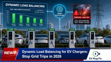
The important limitation is that an EV is not an infinitely adjustable electrical load. Minimum AC charging currents, vehicle behavior, phase configuration and the charger’s control strategy determine how closely the system can follow changing solar production. A well-matched installation can capture a substantial amount of otherwise-exported generation, but buyers should compare those technical details rather than assuming every charger with a “solar” mode behaves the same way. Homes that must coordinate PV output with changing household demand may also benefit from understanding solar EV charging load balancing.
Essential Questions & Expert Answers
Can I charge an EV using only excess solar power?
Yes, if the charging system supports a genuine surplus-only mode and enough excess PV generation is available. Continuous single-phase AC charging generally requires around 6 A, or roughly 1.4 kW at 230 V. Below that level, the system may have to pause unless it supports another strategy such as grid supplementation.
Does surplus solar EV charging require a battery?
No. A compatible charger can use surplus generation directly while the EV is connected. A home battery is optional and may affect which load receives surplus electricity first depending on the energy-management settings.
Do I need a solar charger from the same company as my inverter?
Not always. Some chargers calculate available surplus using independent import/export metering and can therefore work without direct inverter integration. Others require a compatible inverter, meter, gateway or energy-management ecosystem. Check the manufacturer’s integration requirements for the complete system rather than assuming universal compatibility. For one example of how a charger ecosystem handles this, see PV surplus charging with go-e.
Why does my solar charger stop when clouds pass?
If solar surplus drops below the minimum power that the vehicle can accept in the selected charging configuration, a surplus-only system may pause. Whether it stops, waits, switches phases or adds grid electricity depends on the charger, vehicle and selected charging mode.
Can a three-phase EV start solar charging with only 1.4 kW of surplus?
Potentially, but only when the EVSE, vehicle and installation support suitable single-phase operation or automatic phase switching. A charger operating continuously on all three phases at the normal minimum current would require roughly 4.2 kW, while a system able to begin on one phase can start closer to the approximately 1.4 kW single-phase threshold.