
Smart Home Energy Management: Integrating Solar PV, Battery Storage and EV Charging

Smart home energy management coordinates rooftop solar panels, stationary battery storage, and an electric vehicle (EV) charger into one unified system. Without an active control strategy, a household can accidentally export cheap solar power while charging the car from peak-rate grid electricity, overload the main electrical service, or cycle the home battery unnecessarily.
This guide explains the electrical architecture, optimization rules, communication protocols (including OCPP 2.1, ISO 15118-20, OpenADR 3.1, and Modbus), performance KPIs, and commissioning checks needed to build a reliable smart home energy management system (HEMS).
Key Takeaways: Integrating Solar PV, Storage, and EV Charging
- Monitoring Is Not Control: A solar dashboard only displays energy flows; an active EMS dynamically adjusts wallbox current, battery dispatch, and flexible loads within the building’s power budget.
- Mandatory vs. Opportunistic EV Charging: Reliable scheduling guarantees the driver’s departure energy target first, then uses surplus solar or off-peak tariffs to lower costs.
- Local Fallback Matters: Real-time power limiting and solar tracking should run over local meters and controllers rather than depending solely on cloud connections.
- 2026 Protocol Landscape: Standards such as OCPP 2.1 (IEC 63584-210:2025), ISO 15118-20, and OpenADR 3.1 are expanding bidirectional and local DER control, though Modbus RTU/TCP remains essential for inverter and meter integration.
How Smart Home Energy Management Connects Solar Generation, Batteries and Electric Vehicles
A home with rooftop photovoltaic (PV) panels, stationary battery storage, an electric vehicle (EV), a heat pump and an intelligent wallbox is an interconnected electrical system. Each component has its own operating limits, energy requirements and control interface. The challenge is to coordinate them so that the household uses available solar electricity effectively without exceeding the building’s electrical capacity, compromising battery longevity or leaving the vehicle undercharged when it is needed.
This is the purpose of smart home energy management: collecting measurements from different energy assets, applying operating priorities and adjusting electrical loads in response to changing conditions. Rather than allowing every device to operate independently, a supervisory energy management system (EMS) coordinates power flows across the home.
Consider a household with a 10 kWp rooftop PV array, a 10 kWh stationary battery, an 11 kW three-phase wallbox, a heat pump and an EV with a 75 kWh traction battery. These ratings describe different quantities. The PV figure represents peak generation capacity under specified test conditions, the stationary battery’s rating represents stored energy, and the wallbox rating represents maximum charging power. Actual output depends on solar irradiance, equipment limits, temperature, battery state of charge and the electrical installation.
At midday, the PV system might generate 7 kW while the house consumes 1.5 kW. The remaining 5.5 kW could be exported, used to charge the stationary battery or directed toward the EV. If the heat pump starts, household demand rises. If a cloud passes over the array, the controller must reduce charging power or draw electricity from another available source.
There is no universally optimal allocation for every household. A system designed to maximize solar self-consumption might prioritize the EV whenever it is connected, while another might preserve stationary battery capacity for evening consumption or backup power. The appropriate policy depends on electricity tariffs, export compensation, departure schedules, battery warranties, backup requirements and local grid rules.
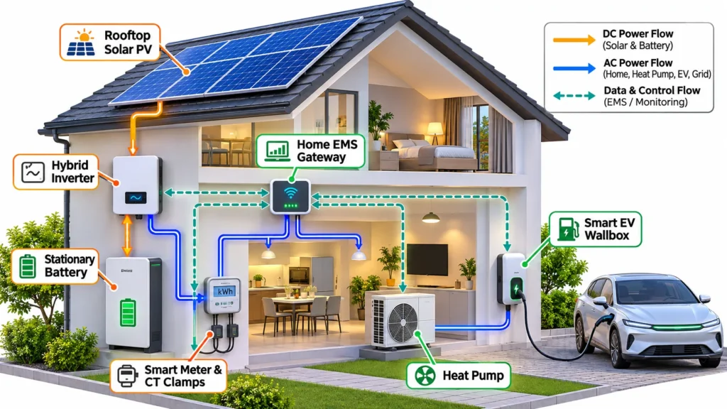
The difference between monitoring and active energy management
Monitoring systems show what the household is generating and consuming. An active EMS uses those measurements to change device behavior. It can regulate the wallbox, modify battery charging or discharging power, adjust compatible heat-pump operation and maintain a safe limit on grid import.
- Measurement: Reads PV generation, grid import or export, household consumption, battery state of charge and EV charging power.
- Decision-making: Applies user preferences, energy prices, equipment limits and departure deadlines to determine which loads should operate.
- Control: Sends charging setpoints or operating commands to compatible inverters, batteries, chargers and household devices.
- Verification: Checks whether measured power follows the requested setpoint and records faults, communication losses or abnormal operating conditions.
- Fallback: Applies a safe operating mode if a meter, network connection or supervisory controller becomes unavailable.
The distinction matters because a dashboard that displays solar surplus does not necessarily control where that energy goes. A genuinely integrated installation needs compatible measurement equipment, control interfaces and a defined authority hierarchy for resolving conflicts between devices.
Why the vehicle changes the household energy equation
An EV is a substantial flexible load, but it is also a scheduled transportation asset. Unlike a stationary battery, which normally remains available at the property, a vehicle may leave for several hours and return with a different state of charge. Energy management must therefore consider mobility requirements rather than treating the vehicle as an unrestricted storage device.
For example, if a driver needs 20 kWh of additional battery energy before leaving at 07:00, a controller cannot simply postpone all charging until solar production begins later that morning. It must calculate the energy requirement, the remaining charging window, conversion losses and the maximum charging power available during that period.
A practical control strategy therefore separates mandatory charging from opportunistic charging. Mandatory charging ensures that the vehicle receives enough energy by its departure deadline. Opportunistic charging uses available solar generation or favorable tariff periods to meet that target at lower cost or with less grid import.
Designing the Electrical Architecture and Measuring Every Energy Flow
PV generation, household loads and stationary storage
A coordinated installation typically includes PV modules, an inverter, a bidirectional or hybrid battery inverter, a stationary battery, an EV charging station, a grid connection meter and a home energy controller. Depending on the architecture, the controller may be integrated into the inverter, wallbox, home automation platform or a separate gateway.
The location of the measurement point is particularly important. A meter or current-transformer sensor installed at the grid connection measures net import and export, while a meter on the PV inverter measures solar output. Additional submeters can distinguish flexible loads from general household consumption. Proper EV charger CT clamp and meter installation ensures the controller does not mistake a change in grid power for a change in solar production.
For example, if PV output is 6 kW, household consumption is 2 kW and the stationary battery is charging at 1.5 kW, approximately 2.5 kW remains available for EV charging before accounting for other losses and control constraints. If the battery stops charging, the available surplus may rise. If household demand increases by 2 kW, the EV charging setpoint must be reduced to avoid additional grid import if zero-import charging is the selected policy.
Actual systems require careful treatment of meter direction, phase assignment, sampling delays and inverter losses. A controller using stale measurements can overestimate available surplus and repeatedly increase and decrease charging power. Appropriate filtering, update intervals, deadbands and ramp limits help prevent this oscillation.
AC-coupled and DC-coupled battery configurations
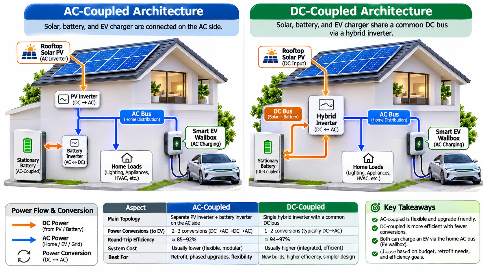
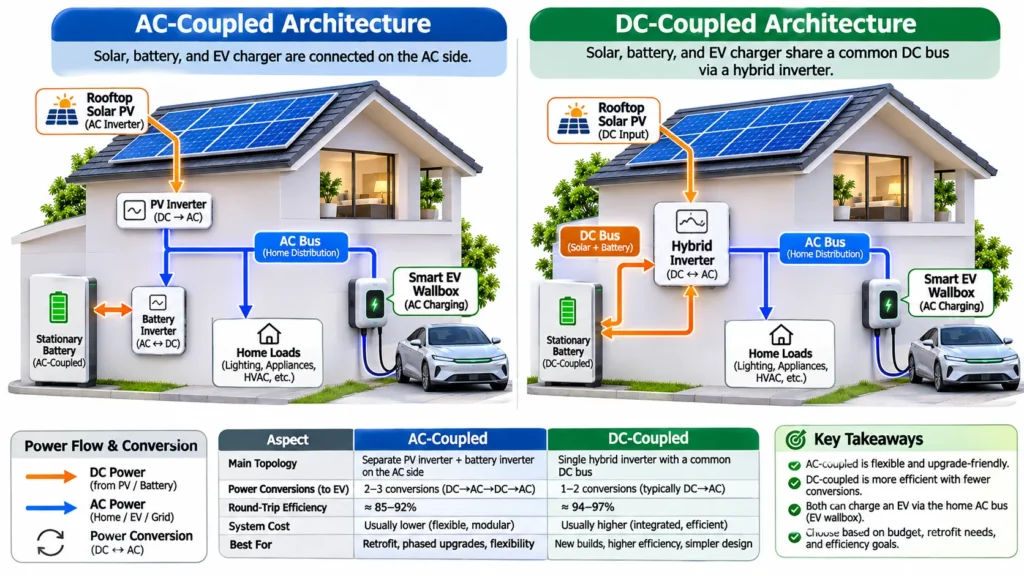
In an AC-coupled system, the PV inverter and battery inverter connect to the home’s AC distribution system independently. This can simplify retrofits because an existing PV installation may accept a separate battery inverter. However, energy moving between DC battery storage and an AC load passes through extra AC-to-DC and DC-to-AC conversion stages.
In a DC-coupled hybrid system, PV generation and stationary battery storage share a DC-side power conversion architecture. Depending on the equipment, this can reduce certain conversion losses and simplify some operating modes. The actual efficiency advantage depends on the inverter topology, voltage ranges, partial-load performance and whether energy is being stored, exported or consumed immediately.
Neither architecture automatically guarantees better EV charging. The wallbox still needs a compatible control path, and the EMS must understand the battery’s charging and discharging constraints. A system can have excellent conversion efficiency yet deliver poor results if its controller fails to coordinate the EV charging schedule with the home’s load profile.
Establishing a safe household power budget
The household power budget defines the maximum permitted grid import or total electrical load. The controller should not rely solely on the wallbox’s nameplate rating: the building’s service capacity, circuit protection, cable ratings, phase allocation and other simultaneous loads determine the permissible operating envelope.
For a simplified single-phase example, a 230 V supply operating at 16 A has an apparent power of approximately 3.68 kVA. At unity power factor, this corresponds to roughly 3.68 kW of active power. A three-phase supply at 400 V line-to-line, 16 A per phase and balanced loading has an apparent power of approximately 11.1 kVA. These calculations are illustrations, not permission to load a circuit beyond its rated continuous operating conditions.
- Service limit: The maximum permitted import based on the connection agreement and installation design.
- Dynamic reserve: Capacity held back for household loads that may start unexpectedly.
- EV charging ceiling: The charging power permitted after accounting for the service limit and active loads.
- Phase constraints: The current permitted on each phase, particularly where household loads are unbalanced.
- Protective coordination: Circuit breakers, EV charger ground fault and residual-current protection, cable sizing and manufacturer-specified installation requirements.
Where the charger and household loads share a constrained connection, dynamic load balancing for EV chargers increases EV charging power when other loads are low and reduces it when the heat pump, oven or other equipment increases demand. The protection system must remain independent of ordinary software optimization; an EMS is not a replacement for correctly designed electrical protection.
Electrical standards and installation compliance
Charging equipment must be suitable for the local supply, vehicle interface and installation environment. The IEC 61851 family addresses conductive EV charging equipment, including general operating and electrical safety requirements. Installers should consult the applicable edition, local wiring regulations, manufacturer instructions and grid-connection rules rather than assuming that a communication feature guarantees electrical compliance.
The official IEC 61851-1 standard for conductive EV charging systems provides a baseline reference for charging-equipment requirements. Compliance still needs to be assessed for the complete installation, including protective devices, earthing arrangements, cable capacity, environmental conditions and any local requirements for bidirectional operation.
Optimizing Solar Self-Consumption, Battery Dispatch and EV Charging
How a solar-aware charging controller works
A solar-aware controller calculates the difference between available generation and non-flexible household demand. It then adjusts EV charging power according to the selected operating mode, the battery’s state of charge and the driver’s required departure energy.
A simple control rule can be expressed as follows:
Available solar surplus = PV generation − household consumption − other prioritized loads − permitted battery charging power, subject to the selected control policy.
This is an accounting approximation rather than a universal control equation. The sign convention for battery power, the location of each meter, conversion losses and the selected export or backup policy must be defined consistently. If the battery is discharging to support the home, its contribution should not be mistaken for surplus PV generation.
In a zero-export or surplus solar EV charging mode, the controller attempts to keep grid import near zero while allowing EV charging to follow available PV surplus. In a mixed mode, the driver can allow a minimum grid contribution so that charging continues smoothly during brief cloud transients or when solar output is insufficient to maintain the desired charging rate.
Some vehicles and wallboxes impose minimum charging-current limits. A typical AC charging implementation requires approximately 6 A per active phase, although exact behavior depends on the charging standard, equipment configuration and vehicle. For a single-phase 230 V connection, 6 A corresponds to about 1.38 kW at unity power factor. For a balanced three-phase 400 V connection at 6 A per phase, the corresponding active power is about 4.16 kW.
These limits can create a gap between available solar surplus and the minimum power required to start or sustain charging. If surplus is too small, the controller may pause charging, accept a small grid contribution or switch to single-phase operation. Automatic phase switching must be natively supported by the wallbox hardware and installed according to the manufacturer’s requirements; it is not a software-only feature that every charger can perform safely.
Deciding when to charge the stationary battery
Stationary storage and EV charging often compete for the same midday surplus. Charging the stationary battery first preserves energy for evening consumption, reduces later grid imports and supports backup operation where available. Sending surplus directly to the EV is often preferable when the vehicle is parked, needs energy soon and would otherwise require expensive grid charging.
Balancing both priorities effectively—as explored in solar EV charging and load balancing—requires evaluating immediate and future energy needs. A stationary battery at 20% state of charge before an expensive evening peak may deserve priority; a vehicle at 25% state of charge with a long trip scheduled the next morning may deserve priority instead.
Battery state of charge is not a complete measure of capability. The controller should also consider permitted charge and discharge power, temperature, reserve settings, state-of-health estimates and manufacturer restrictions. A battery near its upper state-of-charge limit may accept only a reduced charging rate, while a cold battery may impose stricter limits than its nominal rating suggests.
- Set a minimum stationary battery reserve for essential household loads or backup requirements.
- Use surplus PV to charge the EV when the car is present and its departure target is not already satisfied.
- Apply tariff-aware scheduling when electricity prices vary across the day.
- Avoid unnecessary cycling of stationary storage when direct PV-to-EV charging is available and economically preferable.
- Recalculate priorities when solar forecasts, vehicle availability or household demand changes.
Scheduling against a departure deadline
Smart charging becomes significantly more reliable when the controller knows when the vehicle must leave and how much energy it needs. The required battery energy can be estimated from the desired state-of-charge increase and the usable battery capacity, with allowances for charging losses and uncertainty in the vehicle’s displayed state of charge.
For a simplified example, suppose a vehicle has a usable 75 kWh battery and needs a 20-percentage-point increase. The battery must receive approximately 15 kWh. If the overall charging path delivers 90% of the energy drawn from the supply to the battery, the required grid-side energy is approximately 16.7 kWh. This is an illustrative assumption; real efficiency varies with vehicle, charger, charging power and temperature.
If the vehicle is connected for eight hours, the average supply-side power needed is approximately 2.1 kW. That average does not mean charging can always proceed at that power: minimum charging thresholds, changing solar output, charging losses and the vehicle’s own limits must also be considered.
A practical controller can reserve part of the charging window for solar energy and retain enough flexibility to meet the deadline. If the forecast is poor, it may begin charging from the grid during a lower-price period rather than risk an insufficient battery level the next morning.
Comparing common energy management strategies
| Strategy | Primary objective | Typical control behavior | Main limitation |
|---|---|---|---|
| Solar-only charging | Maximize direct PV use | Adjusts EV power to measured surplus and pauses when surplus falls below the charging threshold. | Charging speed varies with weather and available daylight. |
| Solar plus battery priority | Preserve household energy for later | Charges stationary storage to a defined target before allocating remaining surplus to the EV. | The vehicle may receive less solar energy before departure. |
| Departure-based smart charging | Guarantee required energy by a deadline | Combines vehicle energy demand, available charging time, tariffs and forecast generation. | Requires accurate schedules and reliable control communication. |
| Tariff optimization | Reduce electricity cost | Schedules charging around low-price periods while respecting user-defined energy targets. | Low prices do not necessarily coincide with low-carbon electricity or solar availability. |
| Peak-limited charging | Prevent excessive grid demand | Caps total import and dynamically reduces EV power when household demand rises. | Charging may take longer during high household consumption. |
| Integrated predictive control | Balance cost, solar use, comfort and mobility | Uses forecasts and constraints to coordinate EV charging, stationary storage and flexible loads. | Depends on data quality, compatible equipment and sound fallback behavior. |
Communication Protocols: OCPP, ISO 15118, OpenADR and Local Device Integration
OCPP 1.6J, 2.0.1 and 2.1: Managing the charging station
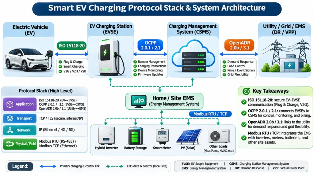
The Open Charge Point Protocol (OCPP) defines communication between a charging station and a charging station management system (CSMS). While widely associated with commercial networks, its role in home energy management depends on the charger firmware, software platform and supported control profiles. An OCPP-compatible wallbox does not automatically communicate with every home battery, PV inverter or smart meter.
OCPP 1.6J uses JSON messaging over WebSocket and remains widely deployed for basic charging profiles, load management and status reporting. OCPP 2.0.1—whose Edition 3 was approved as international standard IEC 63584 in 2024—expands device modeling, security profiles, transaction handling and ISO 15118 integration.
Building on this foundation, the Open Charge Alliance released OCPP 2.1 in January 2025, which was officially published by the IEC as IEC 63584-210:2025 in December 2025, with compliance testing introduced in OCTT Professional in October 2026. OCPP 2.1 retains backward compatibility with 2.0.1 while adding native functional blocks for bidirectional charging (V2X), ISO 15118-20 support and distributed energy resource (DER) control.
Still, the distinction between protocol support and feature support remains critical. A residential charger may implement OCPP only for remote start/stop and cloud telemetry without exposing the fast local control intervals needed for solar-surplus tracking. A home EMS may therefore still rely on a dedicated local interface, Modbus register map or manufacturer API.
For current specification editions and certification details, consult the Open Charge Alliance OCPP protocol documentation.
- OCPP 1.6J: Mature and widely supported for basic smart-charging profiles, though limited in native security and device modeling.
- OCPP 2.0.1 (IEC 63584): Modern production baseline with standardized security profiles, structured device models and ISO 15118-2 support.
- OCPP 2.1 (IEC 63584-210:2025): Adds native bidirectional charging, DER control and ISO 15118-20 functional blocks while staying compatible with 2.0.1.
- Local control vs. cloud path: Local interfaces generally provide lower-latency load adjustments and greater resilience than remote cloud round-trips.
- Security: Requires TLS encryption, certificate management, protected credentials and controlled firmware updates.
ISO 15118 and Plug & Charge
ISO 15118 defines digital communication between electric vehicles and charging equipment. Its capabilities include vehicle-to-charger parameter negotiation, certificate-based Plug & Charge authentication (eliminating RFID cards or apps on supported networks) and advanced energy scheduling.
While ISO 15118-2 handles unidirectional smart charging and Plug & Charge, ISO 15118-20 extends the standard to bidirectional power transfer (AC and DC V2X), wireless charging interfaces and multi-contract support. Regulatory momentum is accelerating adoption: under EU Alternative Fuels Infrastructure Regulation (AFIR) requirements, ISO 15118-20 support becomes mandatory for newly installed or renovated public charging points from January 2027, following ISO 15118-2 mandates introduced in January 2026.
For home energy optimization, vehicle data such as target energy, departure time and charge/discharge limits can improve scheduling accuracy. However, OCPP and ISO 15118 serve different links in the chain: ISO 15118 operates between the EV and the EVSE, whereas OCPP operates between the EVSE and the management backend. The Open Charge Alliance details how these layers interact in its guidance on using ISO 15118 Plug & Charge with OCPP.
OpenADR 2.0b and OpenADR 3.1 for demand response
OpenADR provides a standardized mechanism for communicating demand-response events, dynamic electricity prices and grid-capacity signals between utilities, aggregators and customer energy systems. OpenADR 2.0b remains established in utility-to-cloud demand-response programs.
The newer OpenADR 3 family—most recently updated with OpenADR 3.1.0—introduces lightweight RESTful APIs, JSON payloads and MQTT subscriptions alongside formal program-management models. Crucially for home energy management, OpenADR 3 is designed not only for grid-to-cloud signaling, but also for hierarchical local communication between a customer EMS and downstream chargers, batteries or heat pumps. Note that OpenADR 3.1 is not backward-compatible with 3.0, and the 3.x family complements rather than immediately replaces 2.0b.
Regardless of protocol version, OpenADR delivers grid signals rather than replacing local electrical safety. A home EMS must translate utility price or curtailment requests into device commands while protecting user-defined battery reserves and EV departure deadlines. Further implementation files are available through the OpenADR Alliance specification resources.
Modbus RTU, CAN bus and emerging smart-home standards (Matter, S2, EEBus)
In real-world residential installations, local device telemetry still relies heavily on industrial and building protocols rather than cloud APIs. Modbus RTU (over RS-485) and Modbus TCP (including SunSpec profiles) are widely used to read active power, voltage, current, battery state of charge and inverter limits with sub-second or few-second latency.
Register definitions are not universal across brands. Two inverters may use different register addresses, scaling factors and signed-power conventions. Integration work must strictly follow manufacturer documentation and be verified against a calibrated meter so 500 W is never misread as 5 kW or export mistaken for import.
CAN bus carries high-speed internal telemetry inside vehicles and stationary battery packs, though EV internal CAN traffic is typically restricted at the wallbox interface. Meanwhile, smart-home standards such as Matter (versions 1.3 through 1.5/1.6, which added device clusters for EVSEs, inverters, batteries, heat pumps and tariff data) as well as European protocols like S2 (EN 50491-12-2) and EEBus are gaining traction in specifications—yet certified, multi-vendor Matter-native solar inverters and wallboxes remain limited in commercial deployment. For practical reliability today, documented Modbus, SunSpec or local OCPP interfaces remain the most dependable foundation.
- Modbus RTU / TCP: Primary workhorse for local grid meters and PV/battery inverters when documented register maps are available.
- CAN bus: Essential for stationary battery BMS integration and diagnostics, subject to vendor access rules.
- Matter / EEBus / S2: Emerging interoperability layers for smart-home energy appliances; verify actual hardware certification before relying on them for critical load control.
- Data normalization & monitoring: Converts vendor-specific signs and units into a unified model while detecting CRC errors, stale timestamps and dropouts.
Data Architecture, Forecasting and Control-System Reliability
Building a consistent telemetry model
Smart energy management depends on more than collecting large quantities of data. Each measurement must have a clear meaning, timestamp, unit, source and quality status. A PV inverter’s power reading, a grid meter’s signed active-power value and a battery’s state-of-charge estimate cannot be combined reliably until their definitions and timing are consistent.
A useful EMS data model separates instantaneous power, accumulated energy, electrical measurements, equipment states and forecasts. Power is typically measured in watts or kilowatts; energy is measured in watt-hours or kilowatt-hours. Confusing the two produces incorrect charging estimates and misleading reports.
For example, a steady 4 kW load operating for 30 minutes consumes 2 kWh. A telemetry system that records the power measurement but loses the duration or fails to integrate it correctly cannot calculate energy use accurately. Meter-based energy counters improve accounting, while fast power samples drive dynamic load control.
For a technically robust installation, the data model should include:
- Grid active power, import/export direction, cumulative imported energy and cumulative exported energy.
- PV active power, cumulative generation, inverter operating status and relevant fault codes.
- Battery state of charge, charge/discharge power, temperature and permitted operating limits.
- EV charging power, session state, requested energy, connection status and vehicle-reported limits where available.
- Household load estimates, heat-pump demand and the operating status of other controllable appliances.
- Data timestamps, update intervals, measurement quality, device identity and communication health.
- Tariff periods, energy prices, solar forecasts, departure deadlines and user-defined reserve requirements.
Control intervals, stale measurements and unstable charging
Different components update at different speeds. A local power meter may provide measurements several times per second, while a cloud service may refresh data much less frequently. If the EMS combines readings without accounting for their age, it can calculate a surplus that no longer exists.
Suppose a controller observes 4 kW of surplus and immediately increases EV charging. If the household starts a 2.5 kW appliance before the next measurement arrives, the real surplus falls to approximately 1.5 kW. The wallbox may then draw more from the grid than intended. Repeated rapid corrections can cause charging power to oscillate.
Good control design uses timestamp checks, filtered measurements, hysteresis and ramp limits. Hysteresis prevents a charger from repeatedly starting and stopping when solar surplus fluctuates around the minimum 6 A threshold. A ramp limit restricts how quickly charging power changes, while a stale-data threshold prevents old measurements from authorizing unsafe load increases.
Forecasting solar generation and household demand
Predictive energy management estimates how much solar electricity will be available during the remaining charging window and how much energy the household will need. Forecast inputs can include weather data, historical PV production, time of day, season, household routines, scheduled heat-pump operation and electricity tariffs.
Forecast accuracy matters because an EMS that repeatedly overestimates solar production may delay charging until the last moment. Conversely, a controller that underestimates generation may buy electricity during expensive periods even when sufficient solar power becomes available later.
A practical scheduler evaluates multiple scenarios rather than assuming one forecast is exact, maintaining a conservative grid-charging fallback and updating its plan continuously as real measurements arrive.
Cybersecurity, privacy and degraded operation
Connecting chargers, inverters, meters and vehicles creates additional interfaces that need protection. Remote access, cloud APIs, home automation gateways and local networks can introduce risks if credentials are weak, firmware is outdated or control endpoints are exposed without adequate access restrictions.
Energy systems should separate read-only monitoring from control permissions wherever the architecture permits. Only an authenticated controller should issue charging or battery-dispatch commands, credentials must be stored securely, and firmware updates should follow supported vendor procedures.
The system must also be tested under degraded conditions. If internet access fails, a local controller should continue enforcing the site’s power limit. If the grid meter drops offline, the EMS should stop relying on unverified surplus calculations and revert to a safe charging ceiling or suspend charging.
- Use authenticated communication and supported encryption for remote management.
- Keep device firmware and energy-management software maintained.
- Restrict remote control to authorized accounts and documented interfaces.
- Detect missing, stale or contradictory meter readings before issuing power increases.
- Log command failures, controller restarts, configuration changes and abnormal equipment states.
- Validate recovery behavior after internet loss, power interruptions and device reconnection.
Performance Metrics, Commissioning and Long-Term Optimization
Measuring whether the energy management system is working
A home energy system should be evaluated using measurable outcomes rather than relying on marketing claims that a charger is “intelligent.” Each key performance indicator (KPI) needs a clear measurement boundary and reporting interval. Tracking operational reliability—similar to commercial EV charger uptime and fault monitoring—helps separate nuisance communication dropouts from true hardware failures.
- Solar self-consumption ratio: The proportion of PV generation consumed locally, with storage charging and discharging defined consistently.
- Solar energy delivered to the EV: The measured PV-derived energy attributed to EV charging using a documented accounting method.
- Grid import reduction: The reduction in imported energy relative to a defined baseline, adjusted where practical for weather and mileage.
- Peak demand charge shaving percentage: Percentage reduction in billing-period peak demand relative to a comparable baseline, where demand charges apply.
- First-Time Plug Success Rate (FPSR): Percentage of eligible plug-in attempts that establish the intended session without reconnection or manual reset, distinguishing charger faults from user or vehicle errors.
- Mean Time Between Failures (MTBF) & Mean Time to Repair (MTTR): Average operating time between defined faults and average time required to restore normal operation.
- Connector thermal sensor logs: Temperature readings in °C reviewed alongside current, ambient temperature, duration and manufacturer limits.
- Charging target attainment: Percentage of scheduled departures where the vehicle reaches its requested energy target on time.
- Control accuracy: Difference between commanded and measured charging power over a defined sampling interval.
Monitoring connector temperature and electrical performance
Connector temperature monitoring can help identify deteriorating contacts, excessive resistance, poor mating conditions or abnormal thermal behavior. A temperature trend that rises unexpectedly at a stable current warrants inspection, particularly if it diverges from historical behavior under similar ambient conditions.
Temperature readings depend on sensor placement, ambient temperature, current and equipment design, so installers should evaluate trends against the specific manufacturer’s limits rather than applying one universal threshold. Persistent abnormal heating requires qualified electrical inspection before normal operation resumes.
Calculating peak demand reduction and charging cost
Peak demand reduction is meaningful only when the measurement window matches the utility tariff (commonly 15-minute or 30-minute intervals rather than instantaneous peaks). Likewise, reducing peak demand by 25% does not automatically cut the electricity bill by 25% if fixed charges and energy-rate structures remain unchanged.
Grid energy cost = sum of the energy imported during each tariff period multiplied by the applicable price for that period, plus applicable fees and taxes.
A complete economic assessment should also include lost export credits, battery round-trip conversion losses, EV charging losses and stationary battery degradation before assuming every avoided kilowatt-hour yields a net saving.
Commissioning tests before relying on automation
Testing only on a sunny afternoon leaves critical edge cases unverified. Run a structured commissioning checklist before relying on automated control:
- Verify meter direction: Confirm import, export, PV generation and battery power use consistent sign conventions.
- Test dynamic load balancing: Increase a controlled household load and confirm EV charging throttles down within specified limits.
- Test solar-surplus tracking: Verify smooth adjustment to changing PV output without rapid start-stop cycling.
- Verify departure scheduling: Enter a target kWh and departure time, confirming the scheduler builds a feasible plan.
- Test battery priorities: Verify minimum reserve settings, charge/discharge limits and upper/lower SoC behavior.
- Simulate communication failure: Confirm missing meter readings, Wi-Fi/internet loss and reboots trigger safe fallback behavior.
- Review thermal and fault records: Check that alarms, temperature logs and recovery events record accurately.
- Validate protection independently: Confirm circuit breakers and residual-current devices satisfy electrical standards regardless of EMS software state.
Implementation Roadmap, Compatibility Risks and Future Energy Integration
Planning an upgrade without replacing every component
Most households do not need to rip out existing solar or electrical hardware to introduce smart energy management. Start with an inventory of the PV inverter, battery, wallbox, smart meter and main service capacity to see which devices provide reliable measurements and accept external setpoints.
A phased retrofit can begin with a compatible grid meter and smart wallbox—guided by sound home EV charger installation practices—before layering in stationary storage coordination, dynamic tariffs and flexible heating loads.
Before selecting equipment, confirm the following:
- Whether the wallbox supports local dynamic power control or only cloud-based management.
- Whether the inverter exposes documented local measurements (such as Modbus/SunSpec) and supported control interfaces.
- Whether the battery system permits external dispatch control and which reserve or warranty restrictions apply.
- Whether the smart meter updates fast enough to prevent import spikes during cloud or load swings.
- Whether the controller supports single-phase, three-phase or hardware-supported phase switching safely.
- Whether the system enforces electrical limits offline if internet or cloud services drop.
- Whether protocol compatibility is backed by validated integrations rather than generic marketing claims.
Vehicle-to-home and bidirectional charging
Vehicle-to-home (V2H) extends home energy management by allowing a compatible EV to power household loads during peak rates or outages, while vehicle-to-grid (V2G) exports power to the utility network. Understanding the technical and regulatory distinctions in V2L, V2H, and V2G bidirectional charging is essential before purchasing hardware.
Commercial V2G and V2H offerings have begun rolling out in markets such as Germany (following the elimination of double grid fees at the end of 2025), the United Kingdom and the Netherlands, backed by standards like ISO 15118-20 and OCPP 2.1. Even so, broad multi-vendor interoperability between vehicles, bidirectional chargers and third-party HEMS controllers is still maturing—many early deployments rely on validated vehicle-charger pairings and specific utility tariffs.
Always verify usable capacity realistically: on a 75 kWh EV battery, if 60% is reserved for daily driving, only the remaining margin is available for home backup or arbitrage after accounting for conversion losses and warranty conditions. Homeowners should evaluate carefully whether V2H bidirectional charging is worth the hardware and compliance cost compared with stationary battery storage.
Heat pumps, domestic hot water and other flexible loads
EV charging is only one part of flexible household demand. Compatible heat pumps and domestic hot-water cylinders can store excess daytime solar energy as thermal energy. However, thermal storage introduces distinct constraints—thermal losses, minimum legionella-prevention temperatures, compressor minimum runtimes and occupant comfort—so the EMS must respect appliance safety controls and explicit household priorities.
What to look for in a future-ready home energy system
Long-term flexibility depends on documented local interfaces, upgradeable firmware, clear safety fallbacks and transparent device limits rather than vendor lock-in. Before committing to a platform, verify seven practical questions:
- Can the system reliably meet the vehicle’s departure energy target when solar output is poor?
- Can it enforce a site-wide import limit while high-draw household appliances cycle on and off?
- Does it cleanly distinguish solar surplus from stationary battery discharge and grid import?
- Can it coordinate EV charging and home storage without unnecessary battery cycling?
- Are telemetry, fault records and charging logs accessible locally for troubleshooting?
- Does it revert to a safe fallback limit during meter or internet failures?
- Can new devices (such as a heat pump or bidirectional charger) be integrated later without replacing the entire system?
Frequently Asked Questions About Smart Home Energy Management
Can I charge an EV from solar panels without a home battery?
Yes. A solar-aware wallbox paired with a grid-connection meter or CT clamp can dynamically match EV charging power to excess rooftop PV generation without requiring stationary battery storage. However, charging pauses or draws grid power when clouds pass or solar surplus drops below the vehicle’s minimum charging threshold (typically 6 A per phase).
Is an AC-coupled or DC-coupled battery better for EV solar charging?
Neither automatically guarantees better EV charging. DC-coupled hybrid inverters reduce conversion steps when storing PV energy into a stationary battery, while AC-coupled systems simplify retrofits on existing solar arrays. Since most residential EV wallboxes deliver AC power to the vehicle’s onboard charger, controller coordination and fast meter feedback matter more than coupling topology alone.
What is the minimum solar surplus needed to charge an EV?
Most AC EVs require at least 6 A per active phase to charge. On a 230 V single-phase setup, that equals roughly 1.38 kW of spare solar power; on a balanced 400 V three-phase setup, the minimum threshold is roughly 4.16 kW unless the wallbox supports automatic phase switching or mixed grid-assisted charging.
Do I need OCPP 2.1 or ISO 15118-20 for home solar EV charging?
Not for standard unidirectional solar surplus charging. Today’s home systems rely primarily on local meters, Modbus RTU/TCP, manufacturer APIs or OCPP 1.6J/2.0.1 for dynamic current control. OCPP 2.1 (IEC 63584-210:2025) and ISO 15118-20 become critical if you plan to adopt standardized bidirectional V2H/V2G charging and future utility-interoperable energy services.
Will a smart home energy management system still protect my electrical panel if the internet goes down?
Only if it is engineered with local control and hardware-backed fallback. Dynamic load balancing and grid-import limits should always operate locally via wired meters (such as RS-485/Modbus) inside the property, backed by correctly rated circuit breakers and residual-current protection that operate independently of software.