Does Your Charging Cable Affect Fast Charging Speed in 2026? USB-C & EV Cable Bottlenecks Exposed
Quick Answer
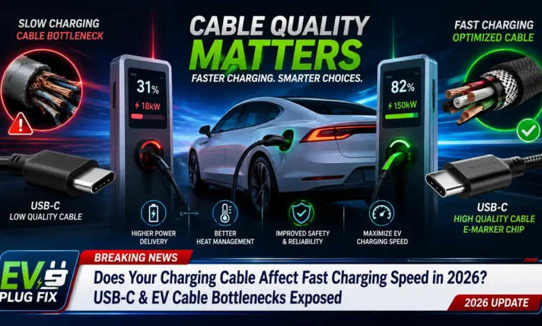
Yes, your charging cable directly affects your fast charging speed. A charging cable is not a passive pipe; it is an active component in the power delivery ecosystem. If a cable cannot handle the required current or fails to communicate with the charger, your device or electric vehicle (EV) will automatically throttle power to prevent overheating and electrical fires.
For consumer electronics, a standard USB-C cable lacking an E-Marker microchip caps charging at 60W (3A), making it impossible to reach 100W, 140W, or 240W fast charging speeds.
For electric vehicles, using a 16-Amp Type 2 cable on a 22kW charging station will cap your charging speed at 11kW, doubling your charging time compared to a 32-Amp cable.
At a Glance: Cable Capability & Speed Matrix
| Cable Type | Max Rated Power | Fast Charging Capability | Real-World Limitation |
|---|---|---|---|
| USB-C (3A Standard) | 60W (20V/3A) | ❌ Limited / Caps High-Power Devices | Cannot fast charge 140W/240W laptops or 45W PPS phones |
| USB-C (5A SPR E-Marked) | 100W (20V/5A) | ✅ Yes (Full 100W) | Limited to 100W max; cannot unlock PD 3.1 EPR (140W–240W) |
| USB-C (5A EPR E-Marked) | 240W (48V/5A) | ✅ Best / Unrestricted | Delivers full theoretical USB PD 3.1 charging speeds |
| EV Type 2 (1-Phase 16A) | 3.7 kW | ❌ Very Slow AC Charge | Adds only ~12–15 miles of range per hour |
| EV Type 2 (1-Phase 32A) | 7.4 kW | ⚡ Standard Home Speed | Ideal for single-phase residential wallboxes |
| EV Type 2 (3-Phase 16A) | 11.0 kW | ✅ Fast AC Charge | Standard output for European residential 3-phase grids |
| EV Type 2 (3-Phase 32A) | 22.0 kW | 🚀 Maximum AC Performance | Unlocks maximum AC charging speed on public infrastructure |
How Fast Charging Works
Fast charging requires a synchronized hardware “handshake” between three distinct components:
- The Power Source: The wall charger, power bank, or EV charging station.
- The Sink Device: Your smartphone, laptop, or electric vehicle.
- The Transmission Medium: The charging cable connecting them.
+-------------------+      Digital Handshake      +-------------------+
|                   | <-------------------------> |                   |
|   Power Source    |                             |    Sink Device    |
| (Charger/Station) | <--- Cable Limits Info ---> |  (Phone/Laptop/EV)|
|                   |      (E-Marker / PP)        |                   |
+-------------------+                             +-------------------+
          |                                                 ^
          |=============== Power Flow (V x I) ==============|
Power delivery is calculated using a straightforward formula:
Power (Watts) = Voltage (Volts) × Current (Amps)
To increase charging speed, fast-charging protocols increase either Voltage (V), Current (I), or both.
However, before high power flows, the charger and device execute a digital negotiation. They query the cable to determine its physical capabilities:
- For USB-C devices: Communication occurs over the Configuration Channel (CC) lines using USB Power Delivery (USB PD 3.1) protocols.
- For Electric Vehicles: Communication occurs over the Control Pilot (CP) and Proximity Pilot (PP) signal pins defined by international standards like IEC 62196 and SAE J3400 (NACS).
If the cable reports a lower rating than the charger or device can handle—or if it fails to communicate entirely—the system safely drops to the lowest common power ceiling supported by the cable.
Why Charging Cables Become the Bottleneck
Cables bottleneck performance due to physical limitations and safety mechanisms designed to prevent electrical disasters.
       CABLE BOTTLENECK MECHANISMS

  +-------------------------------------------------------+
  |  1. Electrical Resistance (R = ρ · L / A)             |
  |     - Thinner wires (high AWG) resist electron flow.  |
  +-------------------------------------------------------+
                            |
                            v
  +-------------------------------------------------------+
  |  2. Thermal Losses & Heat Generation (P_loss = I² · R) |
  |     - High current produces heat; triggers thermal    |
  |       throttling.                                     |
  +-------------------------------------------------------+
                            |
                            v
  +-------------------------------------------------------+
  |  3. Voltage Drop (V_drop = I · R)                     |
  |     - Longer cables lose voltage over distance.       |
  +-------------------------------------------------------+
                            |
                            v
  +-------------------------------------------------------+
  |  4. Protocol Communication Limits                     |
  |     - Missing E-Marker or PP resistor caps current.   |
  +-------------------------------------------------------+
1. Internal Electrical Resistance
Every copper wire offers resistance (R) to electric current, dictated by the formula:
R = ρ × (L / A)
💡 What This Means in Real Life
Think of a charging cable like a water hose. A cheap, thin cable is like a narrow straw: forcing a large volume of water (electricity) through it creates high resistance. If the wire isn’t thick enough, electricity simply cannot flow quickly enough to charge your battery at top speed.
2. Heat Generation and Thermal Throttling
When current passes through a resistant cable, energy is lost as heat according to Joule’s Law:
Ploss = I2 × R
💡 What This Means in Real Life
Because heat increases exponentially with current (I2), doubling the amperage creates 4 times more heat. If your cable head or phone plug gets burning hot, the internal safety sensors will automatically throttle your charging speed down to prevent the cable from melting.
3. Voltage Drop over Distance
As electrical current travels along a cable, resistance causes a drop in voltage by the time power reaches the device:
Vdrop = I × R
💡 What This Means in Real Life
If you use a long, low-quality 10-foot cable, electricity loses strength before it reaches your device. If your charger sends 20V but your laptop receives only 18V due to voltage loss, your laptop will refuse fast charging and drop down to slow charging.
USB-C Cable Limitations
Not all USB Type-C cables are created equal. While two cables may look identical on the outside, their internal wire architecture and electronic components can differ significantly.
USB-C CABLE SPECIFICATION TIERS

[ Standard 60W Cable ] ------------------------> Max 20V / 3A (No E-Marker Required)
[ Premium 100W Cable (PD 3.0 SPR) ] ----------> Max 20V / 5A (Requires 5A E-Marker)
[ Ultra 240W Cable (PD 3.1 EPR) ] ------------> Max 48V / 5A (Requires 240W EPR E-Marker)
Power Specifications: SPR vs. EPR
USB-C specifications governed by the USB Implementers Forum (USB-IF) are categorized into two power ranges:
- Standard Power Range (SPR): Caps out at 20V at 3A (60W) or 20V at 5A (100W).
- Extended Power Range (EPR): Introduced under USB PD 3.1, raising voltage ceilings up to 28V (140W), 36V (180W), and 48V at 5A (240W).
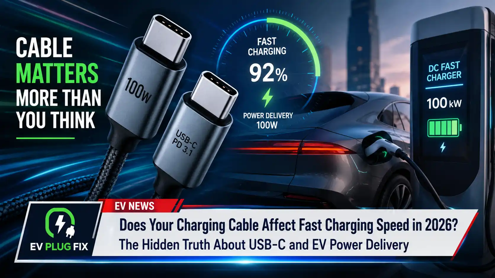
Crucial Rule: Any USB-C cable capable of carrying more than 3 Amps (60 Watts) MUST contain an embedded E-Marker chip. If you use an un-chipped standard USB-C cable with a 140W or 240W charger, your maximum power output will be locked at 60W.
Data Bandwidth vs. Power Delivery
A common misconception is that high data transfer speeds equal fast charging capabilities. This is false:
- USB 2.0 Charge-Only Cables: Contain few internal wires (VBUS, GND, CC, D+, D-). They can support up to 240W charging if equipped with an EPR E-Marker, despite having slow 480 Mbps data transfer rates.
- High-Speed USB4 / Thunderbolt 4 Cables: Packed with coaxial pairs for 40 Gbps bandwidth. However, if they lack a 5A E-Marker chip, their power delivery is restricted to 60W.
EV Charging Cable Limitations
Electric vehicle charging cables encounter similar physical bottlenecks, but at much higher power levels. EV performance hinges on cable phase configurations, physical current limits, and communication protocols.
AC EV CHARGING CABLE BOTTLENECKS (230V / 400V Grid)

  1-Phase 16A Cable ===> [  3.7 kW Max ] (Slowest)
  1-Phase 32A Cable ===> [  7.4 kW Max ] (Standard Home Single-Phase)
  3-Phase 16A Cable ===> [ 11.0 kW Max ] (Standard Commercial/Industrial)
  3-Phase 32A Cable ===> [ 22.0 kW Max ] (Maximum AC Fast Speed)
AC Charging Cables (Mode 3 / Type 2 / NACS)
When charging on Alternating Current (AC), your vehicle relies on its Onboard Charger (OBC) to convert AC electricity into Direct Current (DC) for the battery. However, the external charging cable limits how much current reaches the OBC.
EV charging cables are categorized by amperage and phases:
- Single-Phase 16A Cable: Max output of 3.7 kW (230V × 16A).
- Single-Phase 32A Cable: Max output of 7.4 kW (230V × 32A).
- Three-Phase 16A Cable: Max output of 11 kW (400V × 16A × √3).
- Three-Phase 32A Cable: Max output of 22 kW (400V × 32A × √3).
Real-World EV Bottleneck: If your EV features a 22kW Onboard Charger (such as a Porsche Taycan or Audi e-tron) and you plug into a 22kW public station using a lightweight 16A 3-phase cable, charging performance will be restricted to 11kW. To understand power tiers across AC setups, read our EV Charger Comparison Guide.
DC Fast Charging Cables (CCS1, CCS2, NACS)
DC Fast Chargers bypass the onboard vehicle charger, feeding power directly into the high-voltage battery pack. To deliver speeds between 150kW and 500kW, current ratings must reach 350A to 500A+.
At these extreme currents, conventional copper cables would need to be impractically thick and heavy. To maintain usability:
- Liquid-Cooled Cables: High-power DC chargers use active liquid cooling channels (circulating synthetic oil or glycol mixtures) directly inside the cable bundle to dissipate heat from smaller conductors.
- Thermal Throttling: If the cooling loop fails or ambient temperatures spike, temperature sensors at the connector nose signal the station to drop output, slowing your charging speed. Learn more about DC dynamics in our breakdown of DC Fast Charging Speed.
What Is an E-Marker Chip?
An E-Marker (Electronically Marked Cable Assembly / EMCA) is an integrated circuit embedded inside one or both connector shells of a USB-C cable.
INSIDE AN E-MARKED USB-C CABLE CONNECTOR

 +---------------------------------------------------------+
 |  USB-C Plug Shell                                       |
 |                                                         |
 |   +---------------+   VCONN Power Line                  |
 |   |               |<-----------------------+            |
 |   | E-Marker Chip |                        |            |
 |   |  (ID & Specs) |<--- CC Line (Data) --->|  To Device |
 |   +---------------+                        |            |
 |           |                                |            |
 |   +-------------------------------------------------+   |
 |   | VBUS Power Lines (20AWG Heavy Copper Wire)     |   |
 |   +-------------------------------------------------+   |
 +---------------------------------------------------------+
How the E-Marker Communication Protocol Works
- Plug-In: When you connect a USB-C cable, the charger supplies a low control voltage (5V) via the VCONN pin to power the E-Marker microchip.
- Query: The charger reads the E-Marker’s internal ROM via the Configuration Channel (CC) line.
- Data Return: The E-Marker responds with structural data parameters including Max Amperage (3A vs. 5A), Max Voltage (20V–48V), USB PD protocol generation, and cable resistance profile.
- Negotiation: The power source and host device review these specs. If the cable reports a 3A rating, power delivery locks at 60W max, regardless of whether the power brick is rated for 140W or 240W.
       E-MARKER HANDSHAKE FLOWCHART

   Charger Detects Cable Connection
                  |
                  v
   Supplies 5V via VCONN Pin to Cable
                  |
                  v
   Reads ROM Data on Configuration Channel (CC)
                  |
    +-------------+-------------+
    |                           |
[ Valid 5A / 240W ]     [ No E-Marker / 3A ]
    |                           |
    v                           v
Negotiates High Power   Caps Output at 60W Max
 (100W - 240W Range)    (20V / 3A Ceiling)
Signs Your Cable Is Limiting Charging Speed
If you suspect your charging setup is not delivering its advertised performance, look for these key symptoms of cable bottlenecking:
- 🔥 Excessive Cable Connector Heat: The plastic housing at the connector end becomes burning hot to the touch during the first 10 minutes of charging. This indicates severe contact resistance or insufficient copper gauge.
- 📉 Charging Starts Fast Then Drops Rapidly: Your device shows “Fast Charging” or “Super Charging” for 2–3 minutes, then suddenly drops down to standard charging as thermal protection kicks in.
- 💻 Charger Displays 60W Instead of 140W/240W: Connecting a high-power power bank or laptop wall adapter with an un-chipped cable locks output at exactly 20V/3A (60W).
- 🚗 EV Charges at 7.4kW or 11kW on a 22kW Station: Plugging your 22kW-capable EV into a 22kW public AC charger with a 16A or single-phase cable caps performance far below the station’s capacity.
- ⚡ Intermittent Disconnections under Heavy Load: The device continuously connects and disconnects when battery levels are low (high current draw phase) but stays connected when the battery is near 90% (low current draw phase).
How to Test Your Charging Cable (Real-World Diagnostic Methods)
To verify whether a cable meets its advertised specifications, professional testing equipment and diagnostic tools can be used to read E-Marker chips and measure electrical parameters directly.
1. E-Marker Chip Analysis
Using a specialized hardware USB inline tester (such as the ChargerLAB Power-Z KM003C or FNIRSI FNB58), plug the cable into the tester without connecting a phone. The tester reads the E-Marker ROM data over VCONN and displays vendor credentials, maximum current rating (3A vs 5A), and supported USB PD specification (SPR vs EPR 240W).
2. Voltage Drop Measurement
Connect an electronic load bank through the USB meter. Record voltage at 0 Amps ($V_0$), then increase current draw to 5 Amps ($V_5$). Calculate internal wire resistance:
R = (V_0 - V_5) / 5A
A high-quality 1-meter 240W cable should maintain internal resistance below 0.08 Ohms.
3. EV Cable Pilot Resistor Test
Using a digital multimeter set to Resistance ($\Omega$), measure the resistance between the Proximity Pilot (PP) pin and the Protective Earth (PE) pin inside the Type 2 plug handle. A reading of 220 $\Omega$ confirms a 32A rating; a reading of 680 $\Omega$ confirms a 16A cable restriction.
Wire Gauge Explained
American Wire Gauge (AWG) is the standard measuring unit for electrical conductor cross-sections.
AWG WIRE CROSS-SECTION COMPARISON

  28 AWG  (O) -------- [ Thin Wire | High Resistance | 0.5A - 1A ]
  24 AWG  ( O ) ------ [ Medium Wire | Moderate Loss | 2A - 3A ]
  20 AWG  (  O  ) ---- [ Heavy Copper | Low Loss | 5A High-Power ]
  16 AWG  (   O   ) -- [ Extra Heavy | Minimum Loss | High Amperage ]
Inverse Scale Mechanics
The AWG scale works inversely: a lower numerical AWG value signifies a thicker copper conductor with higher current-carrying capacity.
- 28 AWG Wire: Very thin (0.08 mm²). Found in cheap USB cables intended for low current delivery (0.5A – 1A).
- 24 AWG Wire: Medium thickness (0.20 mm²). Standard for basic 3A USB-C cables.
- 20 AWG (or lower): Thick copper (0.52 mm²). Required for 5A (100W–240W) high-current USB PD cables.
Copper Thickness Impact on Performance
Thicker copper conductors reduce overall wire resistance. When sending 5A of current through a 2-meter cable, using 20 AWG wire instead of 24 AWG cuts internal heat losses by more than 50%. This maintains voltage stability and prevents thermal throttling.
Cable Length and Voltage Drop
Physics sets strict limits on how far high-current DC power can travel through copper conductors before performance declines.
           CABLE LENGTH vs. VOLTAGE DROP

 Power Source                                      Device End
   (20.0V)                                          (18.2V)
  +--------+   ==================================>   +--------+
  |  20V   |     3-Meter Cable (High Drop/Loss)      | Low V  |
  +--------+   ==================================>   +--------+
                                                         |
                                                         v
                                              BMS Throttles Speed!
The Voltage Drop Calculation
Voltage drop is calculated using Ohm’s Law:
Vdrop = 2 × I × (ρ × L / A)
Applied Example:
Sending 5 Amps through a standard 3-meter (10ft) USB-C cable using thin 24 AWG copper wire creates an internal resistance of roughly 0.26 Ohms.
Vdrop = 5A × 0.26 Ω = 1.30 Volts
If the charger transmits 20.0V, the voltage reaching your device drops to 18.70V. When input voltage falls below critical thresholds, your device’s battery controller initiates safety measures: it either requests higher amperage (generating heat) or shifts down to a lower voltage profile, reducing total charging power by 30% to 50%.
Current Rating (16A vs 32A)
Current handling capacity is a key hardware limit for both USB-C and Electric Vehicle charging systems.
CURRENT RATING MATRIX

      USB-C ECOSYSTEM                  EV AC ECOSYSTEM
 +-----------------------+        +-----------------------+
 | 3-Amp Max Cable       |        | 16-Amp Single/3-Phase |
 | (Max 60W Power Limit) |        | (Max 3.7kW - 11kW)    |
 +-----------------------+        +-----------------------+
             |                                |
             v                                v
 +-----------------------+        +-----------------------+
 | 5-Amp Max Cable       |        | 32-Amp Single/3-Phase |
 | (100W - 240W Range)   |        | (Max 7.4kW - 22kW)    |
 +-----------------------+        +-----------------------+
Proximity Pilot (PP) Resistor Coding in EV Cables
In EV Type 2 (IEC 62196) charging cables, a fixed resistor is wired into the plug handle between the Proximity Pilot (PP) pin and the Protective Earth (PE) conductor. The EV charging station measures this resistance to determine the maximum safe current limit of the cable assembly:
- 1500 Ω Resistor: Identifies a 13A cable.
- 680 Ω Resistor: Identifies a 20A cable.
- 220 Ω Resistor: Identifies a 32A cable.
- 100 Ω Resistor: Identifies a 63A cable.
If you plug a 22kW-rated EV into a 22kW charging station using a cable with a 680 Ω PP resistor (20A limit), the charging station reads this resistance value and caps output to 20A (13.8 kW) to protect the wire from overheating.
Real Charging Examples
Scenario 1: Laptop Fast Charging (16-Inch MacBook Pro)
- Power Adapter: Apple 140W USB-C GaN Power Supply.
- Target Device: MacBook Pro 16″ (supports 140W USB PD 3.1 EPR charging).
- Test A (Standard 60W USB-C Cable): Charger detects no E-Marker chip, locking power delivery at 20V / 3A (60W). Charge time to 80%: 1 Hour 55 Minutes.
- Test B (Certified 240W USB PD 3.1 EPR Cable): Charger detects EPR E-Marker chip, authorizing 28V / 5A (140W) power delivery. Charge time to 80%: 35 Minutes.
MacBook Pro 16" Fast Charge Test
+-------------------------------------------------------------+
| 60W Cable  | [======== 115 Mins to 80% ========]            |
| 240W Cable | [==== 35 Mins to 80% ====]                     |
+-------------------------------------------------------------+
Scenario 2: High-End Smartphone (Samsung Galaxy S24 Ultra / iPhone 16 Pro)
- Power Adapter: 45W USB PD 3.0 PPS Wall Charger.
- Target Device: Samsung Galaxy S24 Ultra (supports 45W Super Fast Charging 2.0 requiring 9V/5A via PPS).
- Test A (In-box standard 3A USB-C Cable): Power caps at 9V / 3A (27W) because the cable lacks a 5A rating chip.
- Test B (5A / 100W E-Marked Cable): Power delivery reaches 9V / 5A (45W).
- Performance Gain: Charging speed improves by 38%, saving over 25 minutes.
Scenario 3: Electric Vehicle (Hyundai Ioniq 6 on 22kW Public Charger)
- Charging Station: Public AC Station rated for 22kW (3-Phase 32A at 400V).
- EV Capability: 11kW Onboard Charger (3-Phase 16A maximum intake).
- Test A (Using a lightweight 1-Phase 32A Cable): Station passes only 1 phase, dropping output to 7.4kW.
- Test B (Using a 3-Phase 32A Cable): Full 3-phase delivery is enabled, saturating the car’s OBC at its full 11kW limit.
- Time Saved: Full charge time drops from 10.5 hours to 7 hours.
Comparison Tables
Table 1: USB-C Cable Specifications and Power Limits
| Cable Class | Max Voltage | Max Amperage | Max Power Output | E-Marker Required? | USB PD Version | Primary Use Case |
|---|---|---|---|---|---|---|
| Standard USB-C | 20V | 3A | 60W | No | USB PD 2.0 / 3.0 | Smartphones, Tablets, Kindle |
| High-Current SPR | 20V | 5A | 100W | Yes (5A Chip) | USB PD 3.0 SPR | Mid-range Laptops, 65W–100W PCs |
| EPR Generation 1 | 28V | 5A | 140W | Yes (EPR Chip) | USB PD 3.1 EPR | MacBook Pro 16″, High-End Workstations |
| EPR Generation 2 | 48V | 5A | 240W | Yes (EPR Chip) | USB PD 3.1 EPR | Gaming Laptops, Power Stations, Monitors |
Table 2: EV AC Charging Cables (Type 2 / IEC 62196)
| Cable Specification | Phase Count | Rated Amperage | Max Power Output (230V/400V) | PP Resistor Value | Ideal EV Application |
|---|---|---|---|---|---|
| Single-Phase 16A | 1-Phase | 16A | 3.7 kW | 680 Ω | Plug-in Hybrids (PHEVs), Slow Home Charge |
| Single-Phase 32A | 1-Phase | 32A | 7.4 kW | 220 Ω | Standard Single-Phase Home Wallboxes |
| Three-Phase 16A | 3-Phase | 16A | 11.0 kW | 680 Ω | European Residential 3-Phase, Tesla Model 3/Y |
| Three-Phase 32A | 3-Phase | 32A | 22.0 kW | 220 Ω | Commercial Charging, EVs with 22kW OBC |
Table 3: Power Loss and Voltage Drop Over Cable Distance (5A DC Current)
| Wire Gauge (AWG) | Cable Length | Total Loop Resistance | Voltage Drop at 5A | Power Loss as Heat | Power Delivery Efficiency |
|---|---|---|---|---|---|
| 24 AWG (Thin) | 1m (3.3 ft) | 0.17 Ω | 0.85 V | 4.25 W | 95.75% |
| 24 AWG (Thin) | 3m (10 ft) | 0.51 Ω | 2.55 V | 12.75 W | 87.25% (Throttling Risk) |
| 20 AWG (Thick) | 1m (3.3 ft) | 0.068 Ω | 0.34 V | 1.70 W | 98.30% |
| 20 AWG (Thick) | 3m (10 ft) | 0.204 Ω | 1.02 V | 5.10 W | 94.90% |
Table 4: Pros & Cons: Premium Heavy-Duty Cables vs. Cheap Standard Cables
| Feature / Metric | Premium High-Wattage Cable (E-Marked / Heavy AWG) | Budget Generic Cable (No Chip / Thin AWG) |
|---|---|---|
| Charging Speeds | Maximum possible (Up to 240W USB / 22kW EV) | Bottlenecked (60W USB / 3.7kW–7.4kW EV) |
| Thermal Performance | Runs cool; minimal heat generation | Heats up quickly; triggers thermal throttling |
| Hardware Safety | Built-in over-current & thermal protection | Risk of melted plugs, short circuits, or fire |
| Longevity & Durability | Heavy strain relief, braided jackets, thick shielding | Easily splits, kinks, or breaks internally |
| Upfront Cost | Higher initial investment ($15–$40 / $150–$250 EV) | Very cheap ($3–$8 / $60–$90 EV) |
Recommended Certified Cable Manufacturers
When selecting charging cables for high-wattage electronics or electric vehicles, picking tested, fully certified brands ensures safety and performance compliance.
Consumer Electronics (USB-C)
- Anker: Industry leader in GaN power delivery and 100W/240W bio-braided cables with integrated E-Markers.
- Belkin: Official Apple retail partner providing USB-IF certified cables rigorously tested for voltage drop and compliance.
- Cable Matters: Excellent technical specs, offering full USB4 40Gbps + 240W EPR combo cables with detailed chip listings.
- UGREEN: Reliable high-wattage 100W/240W cables featuring durable strain reliefs and anodized aluminum shells.
- Baseus: Affordable certified 100W/240W digital display cables showing real-time wattage draw.
Electric Vehicle Cables (Type 2 / NACS)
- Mennekes: Original designer of the Type 2 European standard connector; benchmark for AC Mode 3 cables.
- Phoenix Contact: Industrial-grade EV cables featuring ergonomically molded handles and silver-plated contacts.
- Lapp Mobility: High-performance lightweight 32A 3-phase charging cables engineered for extreme cold/heat resilience.
- Duosida / Zappi: Trusted consumer EV charging cables compliant with IEC 62196 safety requirements.
Common Myths
Myth 1: “If a cable fits into the port, it will charge at maximum speed.”
Fact: Universal physical fit does not mean universal electrical performance. USB-C and EV connectors share standardized physical dimensions, but internal copper wire gauges, pin layouts, and e-marker chips vary. An un-chipped USB-C cable fits into a 140W laptop, but power output will cap at 60W.
       PHYSICAL FIT ≠ ELECTRICAL CAPABILITY

 Plug Fits Port?  === YES ===> Connection Established
                                      |
 Digital Handshake? === NO  ===> LOCKED AT 60W SLOW CHARGE!
Myth 2: “Thicker cables charge faster purely because they are thicker.”
Fact: Outer cable thickness is often an illusion created by thick PVC insulation or decorative nylon braiding. True electrical capacity depends on the internal cross-sectional area of the copper wires (AWG) and the presence of verified controller microchips.
Myth 3: “A 240W fast-charging cable will damage small devices like wireless earbuds.”
Fact: Power is pulled by the device, not pushed by the charger or cable. Connected devices request only the exact current (I) and voltage (V) they require. Using a 240W-rated USB-C cable to charge a 5W smartwatch case is completely safe.
Myth 4: “All EV charging cables are passive copper lines without intelligence.”
Fact: EV cables feature embedded Proximity Pilot (PP) resistor loops and internal signal pathways that tell the charger’s controller the safe continuous current limit of the wire assembly.
Myth 5: “Gold-plated connectors make cables charge significantly faster.”
Fact: Gold plating resists oxidation and corrosion over thousands of insertion cycles, but it does not increase electrical current capacity or bypass protocol limits enforced by E-Marker chips.
⚠️ WARNING: Fake E-Marker Chips & Uncertified Cables
Low-cost online marketplaces are flooded with uncertified USB-C cables featuring cloned or hardcoded E-Marker chips that report a 5A capacity without using the required 20 AWG heavy copper wiring.
The Danger: When connected to a 100W+ charger, the system attempts to push 5 Amps through thin 24 AWG wire. The cable cannot handle the thermal load, leading to melted connector heads, short circuits, or fire hazards.
Prevention Tip: Always purchase cables certified by the USB-IF (for USB devices) or compliant with IEC 62196 / SAE J3400 standards (for electric vehicles). Look for official certification logos on product packaging.
Buying Guide
To avoid performance bottlenecks, select your cables based on your specific use cases and technical requirements.
                    QUICK BUYING DECISION TREE

      What device are you trying to power?
                       |
        +--------------+--------------+
        |                             |
  Consumer Electronics         Electric Vehicle
        |                             |
  Check Wattage Target         Check Onboard Charger (OBC)
        |                             |
  +-----+-----+                 +-----+-----+
  |           |                 |           |
<60W        >100W            Single-Phase  3-Phase Grid
  |           |                 |           |
Standard    Buy 240W PD 3.1   7.4kW 32A   22kW 32A
3A Cable   E-Marked Cable     1-Phase Cable 3-Phase Cable
1. Choosing the Right USB-C Cable
- For Smartphones & Accessories (Under 60W): Standard 3A USB-C to USB-C cable (24 AWG or 26 AWG wire). Up to 2 meters without noticeable performance loss.
- For High-Performance Laptops & Fast Power Banks (65W to 240W): Must be explicitly labeled USB PD 3.1 Extended Power Range (EPR) supporting 240W / 5A with an integrated E-Marker Chip (minimum 20 AWG power lines). Keep under 1.5 meters (5 ft) to minimize voltage drop.
2. Choosing the Right EV AC Charging Cable
- For Home Wallboxes & Single-Phase Grids (7.4kW Limit): Purchase a Single-Phase 32A Type 2 EV Cable. Ensures full 7.4kW throughput while remaining lightweight. For home safety and installation compliance, review our guides on EV Charger Safety Setup and EV Charger Permit Requirements.
- For Commercial Chargers & 3-Phase Infrastructure (11kW to 22kW Limit): Purchase a 3-Phase 32A Type 2 EV Cable (rated for 22kW). Future-proofs your vehicle setup even if your current EV only accepts 11kW. If you use smart solar charging modes at home, read our guide on PV Surplus Charging Modes.
Best Practices & Common Mistakes
Best Practices Checklist
- ✅ Verify Cable Wattage Ratings: Ensure the cable wattage rating matches or exceeds your charger’s output capacity.
- ✅ Check for E-Marker Chips on >60W USB-C Setup: Confirm 100W+ USB-C cables contain certified E-Marker chips.
- ✅ Keep High-Power Cables Short: Use shorter lengths (under 1.5m for USB, under 5m for EV) to minimize voltage drop.
- ✅ Match EV Cable Amperage & Phase Specs: Pair 22kW 32A 3-Phase cables with high-power AC public charging hubs.
- ✅ Choose Certified Manufacturers: Buy cables with USB-IF, CE, UL, or TÜV safety certifications.
- ✅ Inspect Plugs Regularly: Check connector ends for bent pins, debris, or discoloration from heat buildup.
Common Mistakes Checklist
- ❌ Assuming physical connector compatibility guarantees fast charging support.
- ❌ Using long, thin extension cords with high-draw chargers or portable EV equipment. (See our Portable EV Charger Comparison Guide).
- ❌ Buying uncertified, ultra-cheap cables for high-wattage power delivery (>100W).
- ❌ Coiling EV or high-current cables during high-power charging sessions. (Coiled cables trap thermal energy and create inductive heat traps).
- ❌ Tugging on the wire cord instead of pulling the plug shell when disconnecting.
- ❌ Overlooking device specs (e.g., using a 240W cable on a phone locked to 18W max).
Frequently Asked Questions (People Also Ask)
1. Can a bad charging cable slow down charging speeds?
Yes. If a cable has thin internal copper wires (high AWG rating), damaged signal lines, or lacks an E-Marker/PP negotiation chip, power output will automatically cap at lower levels (such as 60W for USB-C or 3.7kW for EVs) to prevent electrical fires.
2. How do I know if my USB-C cable supports 100W or 240W fast charging?
Look for official “USB-IF Certified 100W” or “USB PD 3.1 240W” logos on packaging. Alternatively, test the cable with a hardware USB tester like the ChargerLAB Power-Z KM003C to directly read the E-Marker chip data.
3. Why does my 100W USB-C charger only charge my phone at 18W or 27W?
Charging speed is dictated by the host device’s internal Battery Management System (BMS). If your phone’s maximum charging ceiling is 18W or 27W, connecting it to a 100W or 240W charger will still result in a maximum power intake of 18W–27W.
4. Do longer cables charge devices more slowly?
Yes. Longer cables introduce higher internal electrical resistance, causing a voltage drop. If the voltage reaching your device drops below required thresholds, the charging controller will drop down to a lower power tier to keep the system stable.
5. Can an under-rated EV cable damage my electric car’s battery?
No. An under-rated cable will not damage your EV’s battery because the vehicle and station communicate over signal lines to cap power delivery at the cable’s safe maximum rating. However, using a physically damaged cable can cause socket overheating.
6. Is a 240W USB-C cable backward compatible with 65W or 20W chargers?
Yes. USB PD 3.1 EPR 240W cables are fully backward compatible with older USB PD protocols, lower-wattage power supplies, and legacy devices.
7. What is an E-Marker chip in a USB-C cable?
An E-Marker (Electronically Marked Cable Assembly) is an integrated circuit inside the cable connector head that tells the charger and connected device the cable’s maximum safe voltage, current, and protocol capabilities.
8. What happens if I use a 3A USB-C cable with a 140W charger?
The power adapter reads the absence of a 5A/EPR E-Marker chip and locks power delivery at a maximum safe limit of 20V at 3A (60 Watts).
9. What is the difference between single-phase and three-phase EV cables?
Single-phase EV cables pass electricity through one AC line (max 7.4kW at 32A). Three-phase EV cables carry three AC power lines simultaneously, achieving speeds up to 11kW (16A) or 22kW (32A) on compatible AC infrastructure.
10. Why does my charging cable get hot during fast charging?
Current passing through internal copper wire resistance generates heat (Joule heating). Slight warmth is normal during high-power fast charging, but burning hot connectors indicate dangerous contact resistance or insufficient copper wire gauge.
11. Can I use a Thunderbolt 4 cable for 240W fast charging?
Only if the Thunderbolt 4 cable is specifically rated for USB PD 3.1 EPR (240W). Standard Thunderbolt 4 cables without EPR chips are capped at 100W (20V/5A).
12. Does wire thickness (AWG) affect charging speed?
Yes. Lower AWG numbers mean thicker copper conductors with less electrical resistance. Thicker wire gauges (like 20 AWG or lower) maintain voltage stability over distance, enabling full fast charging speeds.
13. How much power loss occurs over a 5-meter EV charging cable?
A high-quality 32A 3-phase 5-meter EV cable experiences negligible power loss (under 1.5% to 2%), provided heavy copper conductors (6 mm²) are used.
14. What is the Proximity Pilot (PP) resistor in an EV charging cable?
The Proximity Pilot (PP) pin contains a fixed resistor inside the connector head that signals the EV charging station the physical current rating (13A, 20A, 32A, or 63A) of the cable assembly.
15. Will a gold-plated USB-C cable charge my phone faster?
No. Gold plating protects against connector corrosion over long-term use, but it does not alter current delivery limits or E-Marker chip protocol handshakes.
16. Are all USB Type-C charging cables the same?
No. USB-C cables vary significantly in internal wire count, copper gauge, data bandwidth capabilities (480Mbps to 40Gbps), and power delivery ratings (60W, 100W, 140W, 240W).
Technical Visual Reference
Below is a schematic breakdown of the physical pin architecture inside a modern USB Type-C connector plug shell:
                  USB TYPE-C RECEPTACLE PINOUT (FRONT VIEW)
 +-------------------------------------------------------------------------+
 | A1   A2   A3   A4   A5   A6   A7   A8   A9   A10  A11  A12 |
 | GND  TX1+ TX1- VBUS CC1  D+   D-   SBU1 VBUS RX2- RX2+ GND |
 |                                                                         |
 | GND  RX1+ RX1- VBUS SBU2 D-   D+   CC2  VBUS TX2- TX2+ GND |
 | B12  B11  B10  B9   B8   B7   B6   B5   B4   B3   B2   B1  |
 +-------------------------------------------------------------------------+
- VBUS (Pins A4, A9, B4, B9): Main power delivery lines.
- GND (Pins A1, A12, B1, B12): Electrical ground return lines.
- CC1 / CC2 (Pins A5, B5): Configuration Channel lines used for digital protocol negotiation and E-Marker power (VCONN).
- D+ / D- (Pins A6, A7, B6, B7): Legacy USB 2.0 signal lines.
- TX/RX Pairs: High-speed differential data channels (used in USB4 & Thunderbolt).
Conclusion
Your charging cable is an active link in the power delivery chain. In 2026, fast charging requires digital negotiations between your charger, cable, and device before high power flows.
- For Consumer Electronics: To reach speeds above 60W, purchase a certified USB PD 3.1 EPR cable with an E-Marker microchip rated for 240W / 5A.
- For Electric Vehicles: Ensure your portable or public AC Type 2 cable is rated for 32-Amps (Three-Phase) to utilize the full capability of 11kW–22kW charging hubs.
Investing in high-quality, certified cables with heavy copper wire gauges ensures safe, reliable, and maximum-speed charging across all your electronics and electric vehicles.