EV Charger CT Installation Guide 2026: Step 5 Current Transformer Setup for Solar & Load Balancing
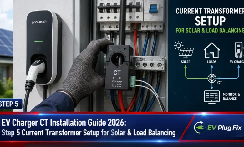
Current transformer (CT) installation represents the single most critical technical step in optimizing your electric vehicle charger for solar PV surplus, and Step 5—attaching these essential sensors—determines whether your entire dynamic load balancing system operates with precision or fails completely.
As EV adoption accelerates across the United States and Europe, homeowners and commercial property managers increasingly turn to solar-integrated EV charging to maximize renewable energy usage and minimize grid dependence. However, without properly installed current transformers, even the most sophisticated EV charging equipment cannot accurately measure power flow from your grid connection, solar inverter, or battery storage system.
This comprehensive technical guide walks through Step 5 of the EV charger installation process, focusing on current transformer attachment for PV surplus optimization. We’ll explore CT types, correct orientation principles, phase-by-phase wiring for three-phase systems, and common pitfalls that can derail your installation. Whether you are a professional electrician or a knowledgeable DIY enthusiast, understanding CT placement is non-negotiable for achieving efficient, cost-effective EV charging.
Let’s dive into the specifics of CT clamps, their role in load management, and precisely how to install them for optimal performance in your EV charging ecosystem.

Why Current Transformers Are the Brain of EV Load Management
A current transformer, or CT, is an instrument transformer that measures electrical current by sensing the magnetic field generated around a conductor and converting it into a proportional signal that a meter, controller, or energy management system can interpret. In practical terms, CTs serve as the sensory nervous system of your EV charging installation, providing real-time data about power consumption and generation that enables intelligent decision-making.
Without accurate CT measurement, your load management controller operates blindly, unable to distinguish between grid consumption, solar generation, and EV charging demand. This lack of visibility forces chargers into conservative modes or, worse, leads to nuisance breaker trips and potential safety hazards.
For modern EV charging installations, CTs enable several critical functions:
- Real-time monitoring of total site current draw across all phases
- Dynamic load balancing that automatically adjusts charger current limits to stay within your property’s electrical capacity
- Solar surplus charging that directs excess photovoltaic generation to your EV battery rather than exporting it to the grid
- Prevention of main breaker trips through proactive current management and load shedding
- Better utilization of existing grid connections without expensive infrastructure upgrades
The stakes are high. Incorrect CT wiring can cause unstable power limits, false readings, or even complete system failure during commissioning. That is why Step 5—attaching the current transformers—demands careful attention to detail and adherence to manufacturer specifications.
Understanding CT Types and Selecting the Right Hardware
Before attaching your current transformers, understanding the available hardware options ensures you have the right tools for the job. CTs come in several form factors, each suited to different installation scenarios.
Split-core (clamp-on) current transformers represent the most common choice for retrofit installations because they can be installed without disconnecting existing cables. These CTs feature a hinged design that opens to clamp around the conductor, making them ideal for electrical panels where interrupting service would be impractical or costly.
Solid-core current transformers require the conductor to pass through the CT window during installation, which typically means disconnecting and reconnecting the circuit. While more labor-intensive, solid-core CTs often offer better accuracy and lower cost than their split-core counterparts.
For most residential and light commercial EV charging installations, split-core CTs from manufacturers like Tesla, ChargePoint, or Electrify America provide the optimal balance of convenience, accuracy, and cost-effectiveness.
Key specifications to verify when selecting CTs include:
- CT ratio—must match your expected current range and controller input requirements
- Burden rating—ensures the CT can drive the input impedance of your load management controller
- Accuracy class—higher accuracy (Class 1 or better) provides more precise power measurements
- Phase mapping—confirm you have the correct number of CTs for your electrical system (three for three-phase, one or two for single-phase configurations)
Pro Tip: Always purchase CTs from your EV charger manufacturer or a reputable electrical supplier rather than sourcing generic components. Matching specifications precisely avoids compatibility issues and ensures your load management controller receives the correct signal levels.
Step 5 Execution: Attaching CTs for Grid Monitoring vs. PV Systems
The most straightforward installation approach involves placing CTs directly at the grid connection point to measure total site import. This method requires three current transformers for three-phase systems—one for each phase. The CTs should be attached to the main incoming conductors where the utility supply enters your property.
For PV surplus optimization, however, you have additional options depending on your system configuration and load management goals. The Teltonika Energy Wiki emphasizes that CT clamps can be configured for different measurement scenarios, including grid monitoring, solar inverter output tracking, and load branch measurement.
Grid Connection Monitoring Setup
When measuring at the grid connection, position each CT on its respective phase conductor. In a three-phase system, phase 1 connects to sensor 1, phase 2 to sensor 2, and phase 3 to sensor 3. This straightforward arrangement measures total site consumption or export, providing the fundamental data for load balancing decisions.
For single-phase installations common in residential settings, a single CT on the line conductor suffices for monitoring import and export. However, if your load management controller supports phase-aware charging strategies, you may still benefit from multi-phase monitoring.
Solar PV and Battery Monitoring Configuration
When incorporating solar generation or battery storage, you can monitor these separate circuits to enable advanced charge management. For a solar inverter, placing CTs on the inverter output conductors allows the load management controller to measure generation independent of site consumption.
The Home Assistant-based EV Solar Charger blueprint from flashg1 demonstrates how a “Main Power Net” sensor expresses negative values in watts for available solar power for charging and positive values for consumed power. This sensor feedback loop enables automatic current adjustments based on real-time generation and consumption.
Similarly, if you have an AC-coupled battery system, placing CTs on the battery output provides visibility into stored energy availability. This data allows your EV charger to prioritize battery discharge for vehicle charging during peak rate periods.
| Measurement Location | CT Placement | Arrow Direction | Use Case |
|---|---|---|---|
| Grid Connection (Mains) | On each phase conductor | From mains towards house | Total site monitoring, load balancing |
| Solar PV Inverter | On inverter output conductors | From inverter to distribution board | Solar surplus charging, export limitation |
| AC Battery System | On battery output conductors | From battery to distribution board | Battery-assisted charging, peak shaving |
| Dedicated Load Circuit (e.g., Boiler) | On circuit conductors | Towards the load | Individual load monitoring, prioritization |
Some advanced installations use separate CTs for the load branch and PV inverter, allowing the controller to mathematically calculate grid import by subtracting generation from consumption [original draft content]. This approach requires careful phase mapping and polarity verification.
CT Polarity and Arrow Direction: The Critical Orientation Guide
Perhaps the most common source of installation errors involves incorrect CT polarity. Every current transformer has a designated direction of current flow, typically indicated by an arrow on the housing. This arrow must point in the direction of current flow as defined by the measurement objective.
Installing a CT backward inverts the polarity of the measured signal, causing negative or unstable load readings that result in unpredictable charging behavior. The Tesla Powerwall installation guide explicitly warns: “Verify the CT(s) are oriented such that the label is facing toward the source (away from the breaker)”.
Direction Rules by Application
Follow these orientation rules for your specific installation scenario:
- Grid Connection (Mains): The arrow should point from the mains toward the house. This measures power flowing from the utility into your property as positive import [original draft content].
- Solar Inverter: The arrow should point from the inverter to the distribution board. This measures solar generation flowing into your electrical system.
- AC Battery System: The arrow should point from the battery to the distribution board. This measures battery discharge as positive supply.
- Dedicated Load Circuits: The arrow should point toward the load (e.g., toward the boiler, air conditioning unit, or other monitored appliance).
Some load management controllers handle polarity differently, interpreting negative readings as export or generation. The EVCM project for Home Assistant, for example, allows users to configure whether positive values represent import or export. However, for most hardware-based systems, maintaining consistent polarity according to the rules above ensures correct operation.
Why Polarity Matters
Patent documentation confirms that “the current transformers CT1 to CT7 have respective polarities. Hence, when the current transformers CT1 to CT7 are not disposed in a predetermined direction (correct direction), the electric energy acquired by the power measurement device has an opposite polarity”.
This means a reversed CT produces readings that are not only inaccurate but potentially the inverse of reality—showing export when you are importing, or vice versa. Such errors can cause your EV charger to increase current when it should decrease, risking overloads and safety hazards.
Double-check orientation during installation, and verify correct polarity during commissioning before tightening CT clamps permanently.
Connecting CTs to Your EV Charger or Load Management Controller
After attaching CTs to the correct conductors with proper orientation, the next step connects them to your EV charger or load management controller. This typically involves terminal connections or RJ45 plugs, depending on the hardware manufacturer.
According to the Qubev EVON0090 installation manual, connecting the CT cable to the charge point requires: “Connect one CT clamp wires to the screw-down connector plugs as shown. Attach the connector to the charger. If connecting to a single-phase charger, the plug should be connected to the two TOP terminals of the connector mounted on the PCB”.
For three-phase systems, connect all three CTs to their corresponding phase inputs on the controller. Each phase must map correctly—Phase 1 CT to Phase 1 input, Phase 2 CT to Phase 2 input, and Phase 3 CT to Phase 3 input. Mixing phase mapping leads to erroneous readings and unstable load balancing.
When extending CT cables, maintain proper connection quality using appropriate connectors. Indra’s CT clamp installation guide recommends joining CT and data cable conductors within two meters of the CT location, using jelly crimps or lever-style connectors such as WAGO, with the connection mechanically protected in a suitable enclosure.
CRITICAL SAFETY NOTE: The Institution of Engineering and Technology warns that “clip-on current transformers offer a quick and easy method for export limitation, and probably all that’s needed for energy management” but emphasizes that CT installations must comply with BS 7671 and local electrical codes. Unless using special SELV-rated CTs, assume secondary circuits are FELV or LV and install them in appropriate enclosures.
Common CT Installation Pitfalls and How to Avoid Them
Even experienced electricians encounter issues when installing current transformers for EV charging systems. Understanding common pitfalls helps you avoid troubleshooting nightmares and ensures your system operates correctly from first power-up.
- CTs installed on wrong cables or phases mixed up—Always label cables clearly during installation and verify mapping through controller diagnostics.
- Incorrect CT ratio—Using CTs with the wrong ratio leads to measurement errors that cause under- or over-charging. Match CT specifications to your installation requirements.
- Reversed polarity—Double-check arrow orientation against the current flow direction. Use a multimeter to verify signal polarity if unsure.
- CT saturation at high loads—Ensure CTs are rated for expected maximum currents to avoid under-reporting during high-demand periods.
- Skipping commissioning verification—Always test and confirm CT readings using the load management controller’s diagnostic interface.
- Missing CT placement and phase mapping documentation—Proper documentation simplifies future troubleshooting and maintenance.
Incorrect CT wiring represents the most frequent issue encountered during EV charger commissioning. As the Teltonika Energy Wiki notes, the installer must “calibrate your CT clamps” using the EV Charging App before the system can operate correctly. This calibration step confirms proper CT installation and loads basic configuration parameters into the controller.
If CT readings appear incorrect during commissioning, systematically check:
- Physical placement on the correct conductors
- Arrow orientation relative to current flow
- Connection integrity at terminals
- Phase mapping between CTs and controller inputs
- Controller configuration matching CT specifications
Commissioning Best Practices
Proper commissioning verifies that CT measurements are accurate and load balancing functions correctly. Start by plugging your EV into the charger without starting a charging session. Use the diagnostic menu in your installer app to check current readings—the system should report the EV’s standby current draw.
Next, start a charging session at reduced current and verify the measured load increases appropriately. If the load reading decreases when you increase charge current, or shows negative values, check CT polarity immediately.
Finally, test dynamic load balancing by introducing significant site loads (e.g., turning on high-power appliances) and confirming the charger reduces current appropriately. The system should maintain total site load below your configured limit.
PV Surplus Optimization: CTs in Action
Once CTs are correctly installed and commissioned, your load management controller can begin optimizing EV charging based on solar PV surplus. The fundamental concept is straightforward: when solar generation exceeds site consumption, the excess power can charge your EV rather than exporting to the grid.
The Home Assistant EV Solar Charger blueprint implements this by monitoring the “Main Power Net” feedback loop sensor, which indicates available solar power for charging as a negative value. The controller adjusts EV charging current to consume available surplus, pausing when cloud cover reduces generation and resuming when the sun returns.
Advanced implementations incorporate additional intelligence. The EVCM project by KriVaTri allows users to “automatically start and stop EV charging based on their preferences (with or without solar export), starts charging when there is enough available power, pauses charging when you start importing too much from the grid, and turns the charging amps up or down to match what you have available”.
This degree of control requires accurate CT measurement at the grid connection, solar inverter output, and sometimes battery storage circuits. The controller uses these inputs to make real-time decisions that maximize renewable energy usage while protecting the site’s electrical infrastructure.
For homeowners with solar PV and battery storage, CT-enabled load balancing can reduce grid import to near zero during sunny periods, dramatically lowering electricity costs and reducing carbon footprint. Commercial installations benefit from reduced demand charges and more predictable energy costs.
Integrating CT-Based Load Management with Smart Home Systems
Modern EV charging installations increasingly integrate with home automation platforms like Home Assistant, enabling sophisticated charge management beyond the capabilities of standalone load management controllers.
The SolaX EV Charger integration, for example, allows users to “monitor EV SOC (provided by car OVMS) and stop charging on set value. 80% most of the time to save car battery”. When combined with CT-measured solar generation, this integration enables:
- Charging only when solar surplus exists and stopping when cloud cover reduces generation
- Prioritizing charging during lowest electricity tariff periods using time-of-use data
- Preconditioning the EV battery for optimal charging efficiency based on weather forecasts
- Automatically adjusting daily charge limits to extend battery life, as the EV Solar Charger blueprint offers by “automatically adjust[ing] to the highest charge limit set within a rainy forecast period”
These integrations require accurate, reliable CT data to function correctly. The feedback loop between CT measurements and charging decisions operates continuously during charging sessions, making proper CT installation essential.
Understanding Dynamic EV Load Balancing principles helps you appreciate why CT accuracy directly impacts system performance and energy savings.
Professional Installation Standards and Safety Considerations
CT installation for EV charging must comply with applicable electrical codes and safety standards. The Institution of Engineering and Technology highlights that “current transformer installation is ramping up with PV inverters and EV charging equipment” but warns that installation quality often falls short of BS 7671 requirements.
Key safety considerations:
- Never open-circuit a CT while current flows through the primary conductor—This creates dangerously high secondary voltages that can cause electric shock and equipment damage.
- Maintain proper IP ratings—As the Qubev manual notes, “a suitable cable gland must be installed to the chargepoint enclosure to accept the CT cable(s) and maintain the IP rating of the enclosure”.
- Use appropriate cable sizes—CT secondary wiring must be sized appropriately for the distance from the CT to the controller.
- Ground equipment correctly—The evplug BCP Series manual emphasizes that “grounding must be installed at the power source and not at the cable entry to the EV Charger”.
For professional installers, using manufacturer-provided installer apps simplifies the commissioning process. The EGO EV Installer App, for example, provides “step-by-step instructions covering mounting, wiring, and fascia cover placement” with “high-quality images and diagrams”. These tools help reduce installation errors and ensure consistent quality.
When planning your installation, consulting a comprehensive Home EV Charger Guide can help you understand the full scope of requirements and best practices.
Essential Questions & Expert Answers
Why does CT orientation matter so much for EV charging?
Can I use generic current transformers with any EV charger?
How many current transformers do I need for a three-phase solar EV setup?
What happens if I install a CT with reversed polarity?
Is a current transformer installation safe for DIY homeowners?
Step 5 of your EV charger installation—attaching current transformers—represents the foundation upon which all load balancing and solar optimization capabilities depend. By following the precise CT placement, orientation, and connection procedures outlined in this guide, you ensure your EV charging system operates with the accuracy and reliability required for efficient, cost-effective electric vehicle charging.
Remember that proper CT installation enables dynamic load balancing, prevents nuisance trips, and maximizes your use of solar PV generation. Take the time to get this step right, and your investment in EV charging infrastructure will deliver years of dependable performance with lower energy costs and reduced environmental impact.
For professional electrical contractors, integrating CT-based load management into your service offerings positions your business at the forefront of the EV charging installation market. As utilities and governments incentivize solar-integrated charging, demand for correctly installed CT systems will only continue to grow through 2026 and beyond.