Control Pilot and Proximity Contact Signals: How EV Charging Handshake Works in 2026
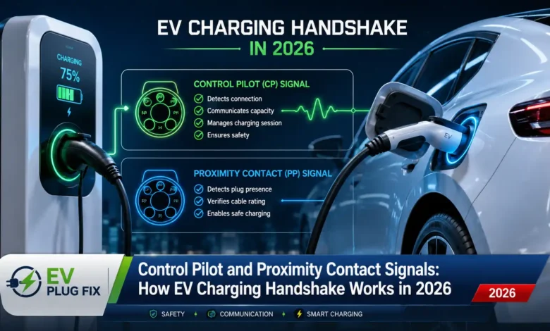
The Control Pilot (CP) and Proximity Contact (PP) signals form the communication backbone of every Level 1 and Level 2 AC charging session, as defined by the SAE J1772 and IEC 61851 standards . They are the silent sentinels that ensure no power flows until the connection is safe and secure, orchestrating a complex handshake that happens in milliseconds.
The Critical Need for a Pre-Charge Handshake
Charging an electric vehicle isn’t as simple as plugging in a smartphone. High-power AC charging introduces significant risks. A typical 7.2 kW single-phase charger or a 22 kW three-phase unit pushes dozens of amperes through the charging cable. If the connector were to separate under load, or if the vehicle’s onboard charger wasn’t ready to receive power, an uncontrolled arc could occur. This would not only damage the expensive hardware but also pose a serious safety risk to users . Understanding these risks is why EV Phase Balancing and proper installation are critical for any home or public charging setup.
The CP and PP signals act as a safety interlock layer, operating entirely outside the power path. They run on low voltage and never touch the high-voltage conductors, but they are the absolute governors of when and how much power is delivered.
What is the Proximity Contact (PP) Signal?
The Proximity Contact signal answers a simple, fundamental question: is the charging connector physically and securely seated in the vehicle’s inlet? This is the first step in the handshake and a primary function of the PP line is to confirm the presence and proper connection of the vehicle, preventing it from driving away during charging .
Inside the charging plug, a small resistor is tied between the PP pin and the protective earth (PE) pin. The vehicle’s inlet reads the resistance across these two contacts and interprets it according to a defined table. This is an elegant, passive identification method .
- SAE J1772 (Type 1): An open circuit (no plug) reads more than 1 kΩ. A fully seated connector drops resistance to 150 Ω. Pressing the release button changes it to 68 Ω, signaling the vehicle to stop current flow before the latch disengages, preventing a hot-unplug event .
- IEC 62196 (Type 2): This standard uses a slightly different resistor ladder (1500 Ω, 680 Ω, 220 Ω, and 100 Ω) to encode both connection status and the cable’s current-carrying capability . This ensures the EVSE does not deliver more current than the cable is rated for, helping avoid overheating .
This is a brilliant mechanical failsafe. The resistor lives inside the molded plug body, requiring almost no active components. It is reliable and inherently safe.
The Control Pilot (CP) Signal: A Bidirectional Communication Channel
While the PP signal is a passive analog indicator, the Control Pilot is an active, bidirectional signaling channel that carries two distinct pieces of information simultaneously. It is the main communication route between the EVSE and the EV, managing the entire charging process .
The EVSE generates a ±12 V square wave on the CP pin at 1 kHz. The duty cycle of this waveform encodes the charger’s current capacity. The formula is straightforward for currents between 6 A and 51 A: available current equals the duty cycle percentage multiplied by 0.6. So, a 25% duty cycle advertises 15 A, and a 50% duty cycle advertises 30 A. This means the vehicle’s onboard charger always knows exactly how much current it is allowed to draw without needing a separate data bus . For those interested in how this integrates with modern smart systems, Smart EV Charging Europe explores how these signals enable grid-responsive charging while maintaining safety.
The vehicle interprets the CP signal through a resistor network inside its inlet. By switching different resistor values in and out, the vehicle pulls the positive peak voltage of the CP waveform down from its nominal +12 V to lower levels, defining the standard charging states.
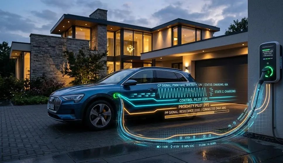
A breakdown of the CP voltage states, showing how the EV communicates readiness to the charging station.
Decoding the Control Pilot States
Here is how those CP voltage states map to the charging process :
| State | Description | Vehicle Action | EVSE Action |
|---|---|---|---|
| A (Standby) | No vehicle connected. | N/A | CP line floats at +12V DC. Contactor is open, no power. |
| B (Connected – Not Ready) | Vehicle connected and detected. | Switches in a 2.74 kΩ resistor, pulling CP peak to ~+9V. | EVSE recognizes a vehicle is present, generates 1 kHz PWM waveform, but contactor remains open. |
| C (Ready to Charge) | Vehicle is ready to accept power. | Switches in a second resistor (1.3 kΩ) in parallel. Combined resistance (~882 Ω) pulls CP peak to ~+6V. | EVSE detects the transition to State C and commands the main power contactor to close. Charging begins. |
| D (Ventilation Required) | Legacy state for older battery chemistries. | Pulls CP to +3V. | EVSE allows charging with forced ventilation. |
| E/F (Error/Fault) | Fault condition detected. | Missing or inverted negative half of CP waveform. | EVSE immediately opens the contactor to halt power flow. |
“A negative peak of −12 V on CP always indicates a fault; the EVSE immediately opens its contactor if it detects a missing or inverted negative half.” — IEC 61851 Standard
The Complete AC Charging Handshake Sequence in 2026
Putting it all together, the complete charging session unfolds in a precise sequence designed for maximum safety .
- Physical Connection: The user inserts the connector. The PP resistor immediately signals “connected” to the vehicle.
- Pilot Generation: The EVSE detects the PP closure and begins generating the CP PWM waveform, advertising its maximum current.
- State B Handshake: The vehicle reads the CP signal, loads the line with a 2.74 kΩ resistor, and confirms State B. This tells the EVSE, “I see you, and I’m running my own pre-charge checks.”
- Vehicle Readiness: The BMS verifies cell voltage, temperature, and isolation resistance. Once ready, it switches in the second resistor, pulling the CP to +6 V — State C.
- Power Delivery: The EVSE detects the transition to State C and commands its power contactor to close. AC power appears on the supply conductors, and the vehicle’s onboard charger begins rectifying it to DC for the battery.
- Continuous Monitoring: Throughout charging, if the vehicle needs to pause (e.g., for thermal management), it returns to State B, and the EVSE opens its contactor within 100 milliseconds .
Inside the Charger: The Hardware That Makes It Work
On the EVSE side, the CP signal is generated by a small dedicated circuit. In many modern charge points, a single microcontroller or a dedicated EVSE controller IC (such as the Atmel ATA6870) handles the entire CP/PP interface. This controller produces the PWM waveform, monitors the incoming peak voltage through an op-amp peak-detector circuit, and drives the main power relay through an isolated gate driver .
The 1 kΩ current-limiting resistor in series with the CP line is a mandatory safety element defined by the standard. It limits any fault current that could flow if the CP pin were shorted to the power conductors.
On the vehicle side, the inlet assembly contains the pull-down resistors, a diode to rectify the CP waveform for measurement, and the switching transistors or relays that change the resistor configuration as the BMS progresses through its checks . When choosing equipment, understanding material quality matters — our EV Charger Materials Guide explains how conductor materials impact long-term reliability and efficiency.
Why This Design Remains the Industry Standard
The elegance of the CP/PP approach is its robust simplicity. The entire system runs on a 1 kHz analog waveform, a handful of resistors, and two voltage thresholds. It is immune to network outages and requires no pairing procedure. If the CP line is severed, the EVSE immediately detects the fault and stays in State A with the contactor firmly open .
This robustness explains why the same fundamental signaling scheme, first published in the early 1990s as part of SAE J1772, continues to underpin virtually every Level 2 AC charging session worldwide today . Even as higher-level protocols like ISO 15118 add digital communication layers for smart charging and Plug and Charge EV Technology, the CP and PP signals remain the essential safety and control foundation on which they are built. For a real-world example of how these systems are deployed, check out the Public EV Fast Charging infrastructure that relies on these same principles at scale.
Understanding CP and PP is therefore not merely an academic exercise. It is the foundation upon which every safety interlock, every smart-charging negotiation, and every grid-responsive charging session ultimately rests. For homeowners looking to implement their own charging solution, EV Wallbox Installation ensures these critical signals are properly wired and configured for safe, reliable daily charging.